140SDO95300S
Description
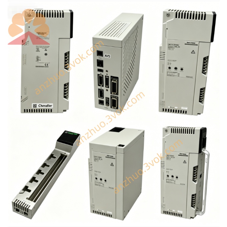
1. Product Overview
2. Key Features
16 safety digital outputs, 24 VDC (19.2–30 VDC operating)
SIL3 certified (IEC 61508), high‑integrity safety systems
Output type: PNP source (positive logic), 0.5 A per channel
Short‑circuit / overload protection, per channel and total
Response time: ≤20 ms (ON/OFF)
Isolation: 1500 Vrms (channel ↔ backplane), 1 min
Hot‑swappable, Quantum rack compatible
Comprehensive diagnostics: overload, short, open, supply fault
Safety data mapping: 4 output words, 6 input words, 1 health word
Conformal coating option for harsh environments
3. Technical Specifications
Digital Outputs
Channels: 16, single‑ended, grouped in 1 bank
Nominal voltage: 24 VDC (19.2–30 VDC operating)
Absolute max: 34 VDC
Output type: PNP source (positive logic)
Current: 0.5 A continuous per channel; total ≤4 A
Voltage drop: ≤0.3 V @ 0.5 A
Leakage current: ≤0.5 mA @ 30 VDC
Response time: ≤20 ms (0→1, 1→0)
Surge current: 2 A for 10 ms
Protection: Short‑circuit, overload, reverse polarity
Electrical
Backplane power: 5 V DC
Current consumption: ≤750 mA @ 5 V
Power dissipation: ≤3 W
Field power: 19.2–30 VDC external (isolated)
Environmental
Operating temp: −25 °C to +60 °C
Storage temp: −40 °C to +85 °C
Humidity: 5–95 % non‑condensing
Altitude: ≤2,000 m
Safety rating: SIL3 (IEC 61508)
Certifications: CE, UL 508, CSA, FM, UL 1604 Class I Div 2, RoHS
Mechanical
Dimensions (W×H×D): 40.34 × 250 × 103.85 mm
Weight: ~0.45 kg
Connector: Pluggable terminal block (16 outputs + common)
4. LED Indicators
| LED | Color | Status | Meaning |
|---|---|---|---|
| PWR | Green | On | Module powered |
| Off | No power / fault | ||
| RUN | Green | On | Module operational |
| Flash | Initialization / self‑test | ||
| FAULT | Red | On | Safety fault / diagnostic trip |
| Off | No fault | ||
| CH1–CH16 | Yellow | On | Channel active (logic 1) |
| Flash | Channel fault (overload/short) |
5. Installation & Wiring
Rack Mounting
Insert module into Quantum rack slot; push until latched.
Hot‑swap supported (rack power ON).
Field Wiring (24 VDC Loads)
+24 V → Module V+ (field power)
**Module OUTx → Load +
Load − → 0 VDC (field ground)
Common → 0 VDC (field ground)
Shield → Earth ground (single point)
Cable: Twisted pair, screened; max 500 m
Separate from high‑voltage / high‑power cables
6. Configuration (Unity Pro)
Unity Pro V7.0+; add 140SDO95300S to hardware list.
Map 4 output words (control) and 6 input words (diagnostics).
Enable diagnostics: overload, short, open, supply fault.
Configure 1oo2 / 2oo2 voting for SIL3.
Download configuration; module runs autonomously.
7. Safety & Diagnostics
SIL3 operation: Continuous self‑tests, cross‑channel comparison, signal plausibility checks.
Fault response: On fault, FAULT LED ON, safety logic sets channels to safe state (de‑energized, user configurable).
Diagnostic coverage: >95% for safe faults (SIL3).
Safety data: Fault flags in process data, health word for system status.
8. Operation & Maintenance
Normal Operation
PWR: ON
RUN: ON
FAULT: OFF
CH LEDs: ON/OFF per output state
Troubleshooting
FAULT ON: Check field power, wiring (short/overload), load failure, or module fault.
CHx Flash: Channel x overload/short; check load and wiring.
No output: Verify backplane power, module seating, configuration, or field power.
Maintenance
Inspect wiring quarterly; clean terminals.
Verify safety diagnostics semi‑annually.
Update firmware via Unity Pro (Schneider Electric website).
9. Safety Notice
Qualified personnel only for installation/service.
SIL3 applications require safety plan, periodic proof tests, and fault response procedures.
Do not open module; no user‑serviceable parts.
10. Compatibility
Quantum CPU: 140CPU65150/67160/68060 and above
Software: Unity Pro V7.0+, Safety Library (SIL3)
Get a Quote