140EHC10500
Description
1. General Description
2. Specifications
2.1 Counter Channels
Number of channels: 5 (independent)
Counter resolution: 32‑bit (signed)
Max input frequency:
100 kHz (5 VDC differential encoder)
20 kHz (24 VDC single‑ended encoder)
Input types: A/B quadrature, pulse/direction, up/down, event
Modes per channel:
Event counter
Differential (quadrature) counter
Period/frequency meter
Watchdog (pulse presence monitoring)
2.2 Digital Inputs (8 points)
Voltage: 24 VDC nominal
Type: Sink (NPN), 7 mA typical
Isolation: 2500 V AC (channel‑to‑backplane)
Response time: ≤ 1 µs
2.3 Digital Outputs (8 points)
Voltage: 24 VDC nominal
Type: Sourcing transistor (PNP)
Current: 0.5 A per channel (max)
Protection: Short‑circuit & overload
Isolation: 2500 V AC
2.4 Power & Environment
Backplane power: 5 VDC
Power dissipation: ≤ 6 W
Operating temperature: 0 °C to +60 °C
Storage temperature: −40 °C to +85 °C
Relative humidity: 5–95 % (non‑condensing)
Certifications: CE, UL, CSA, RoHS
2.5 Mechanical
Form factor: Single slot, Quantum rack
Dimensions (W×H×D): 104 × 40 × 250 mm
Weight: ~0.3 kg
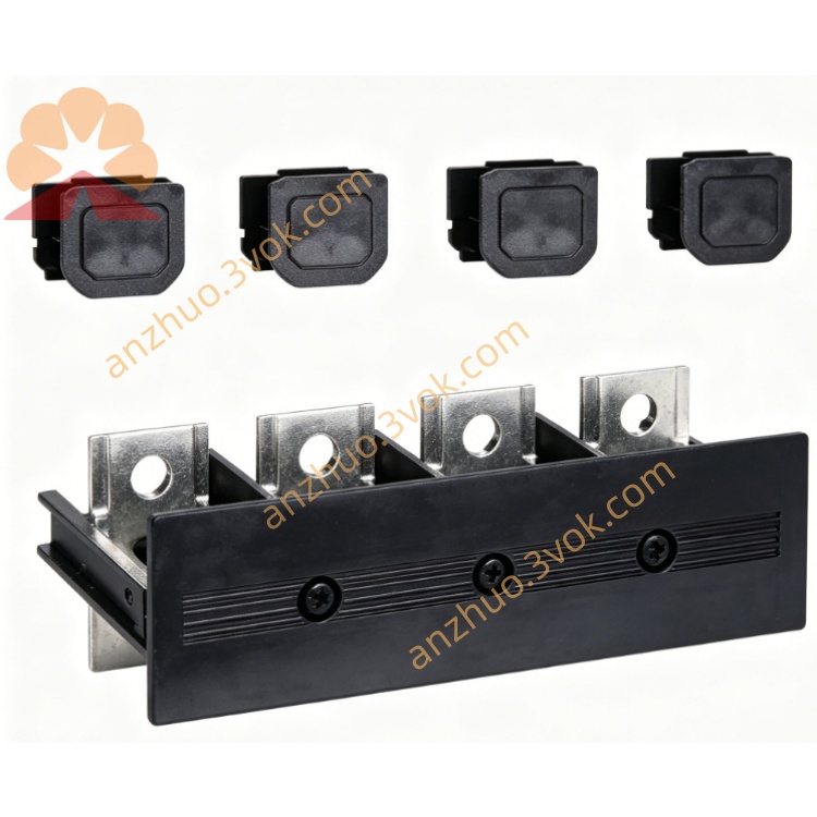
Connector: 40‑pin terminal block (separate order)
3. Operation Modes (per channel)
- Event CounterCounts rising/falling edges; no latch/timer; 32‑bit wrap‑around.
- Differential (Quadrature) CounterA/B phase decoding (×1, ×2, ×4); direction auto‑detect.
- Period/Frequency MeterMeasures pulse period (µs) or frequency (Hz); configurable gate time.
- Watchdog TimerMonitors pulse presence; triggers output if no pulse within preset time (safety).
4. Module Architecture
5 counter channels with dedicated hardware logic
8 DI / 8 DO mapped to Quantum I/O table
LED indicators:
PWR: Green = power OK
RUN: Green = module active
ERR: Red = fault (config, wiring, overload)
CH1–CH5: Green = counting activity
5. Installation
Power off the Quantum rack.
Insert module into any empty slot; push firmly until seated.
Secure front panel screws.
Wire encoders/sensors to the 40‑pin terminal block (shielded cable recommended).
Power on; verify PWR and RUN LEDs are green.
6. Configuration (EcoStruxure Control Expert / Unity Pro)
Add 140EHC10500 to hardware configuration.
For each channel:
Select mode (event, differential, period, watchdog)
Set input type (5 V / 24 V, single‑ended / differential)
Configure preset values, setpoints, and output mapping
Assign 8 DI / 8 DO to I/O addresses.
Download configuration to PLC; check ERR LED.
7. I/O Mapping
Inputs 0–7: 24 VDC sink; read via Quantum input table
Outputs 0–7: 24 VDC sourcing; write via Quantum output table
Counter data: 32‑bit values in PLC memory (per channel: current count, preset, status)
8. Applications
High‑speed pulse counting (encoders, flow meters, tachometers)
Position/speed monitoring (conveyors, machine tools, packaging)
Frequency/period measurement
Event logging & sequencing
Safety pulse monitoring (watchdog)
9. Diagnostics & Troubleshooting
PWR off: Check backplane power; re‑seat module
RUN off: Verify CPU is in RUN; re‑download config
ERR on: Check wiring, encoder voltage, config errors, or output overload
No counting: Verify encoder power, A/B phase wiring, input frequency limit
10. Reference Documents
Official Manual: Quantum using EcoStruxure Control Expert – 140EHC10500 User Manual
Doc No.: 33002491K01000 (Rev 09, Dec 2018)
Software: EcoStruxure Control Expert (Unity Pro) v7.0+
Get a Quote