330980-70-05
Description
I. Model Positioning
330980: High-temperature-specific phase and speed probe, not replaceable by conventional vibration detection probes
70: Narrow side-out structure, suitable for compact installation conditions
05: Integrated 5-meter fixed-length cable, no need for additional extension cables
Usage: High-temperature chamber areas of steam turbines and gas turbines, specifically for phase measurement and speed protection, not for shaft vibration or axial displacement measurement
II. Core Parameters
1. Mechanical Structure
Probe Type: Electric Eddy Current High-Temperature Phase-specific Probe
Installation Thread: 3/8-24 UNF standard specification
Output Form: Side-out narrow-shaped structure
Cable Configuration: Built-in 5-meter integrated cable, cannot be cut or modified
Shell Material: High-temperature-resistant stainless steel, resistant to deformation and oxidation
Protection Grade: IP67, dustproof, waterproof, resistant to oil and corrosion
2. Electrical Characteristics
Measurement Principle: Non-contact Eddy Current Induction Detection
Adapter Compatibility: 330180 Standard Type, 330181 High-Temperature Type
Sensitivity: 7.87V/mm
Frequency Response: 0~10kHz, covering the entire unit's speed range
Pulse Quality: Clear signal edges, no lost pulses, no interference noise
Power Supply: -24VDC ±10%
3. Environmental Tolerance
Probe Working Temperature: -40℃~+175℃
Cable Working Temperature: -40℃~+125℃
Anti-Vibration Grade: 10g (10~1000Hz)
Small temperature drift, stable signal without offset distortion in high-temperature conditions
4. System Adaptation
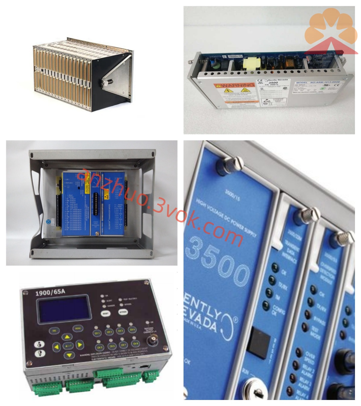
Adaptable Rack: 3300 TSI, 3500 TSI Monitoring System
Adaptable Module: 3500/50E, 3500/50M Speed Phase Module
Connection Adaptation: Direct connection to the same specification preamplifier interface
III. Installation Tips
1. Installation Gap
Standard installation gap control: 1.0~1.5mm
Preferred tested workpiece: 4140 steel, detection surface size larger than probe's three times diameter
Proximity of the probe to 5mm or more clearance to avoid interference from surrounding metals during detection
2. Wiring Standards
Use three-wire connection, core wire as signal end, inner shield as common end, outer shield as grounding end
Shielded cable is only grounded at the preamplifier end to prevent circulating current interference with the signal
3. Installation Steps
Clean the installation hole and surface burrs, oil stains, impurities of the measured object
Rotate the probe to the fitting end face and retreat 1.25mm for standard gap
Tighten the anti-loosening nut, maintain a tightening torque of 8~10N・m
Arrange the wiring neatly, the minimum bending radius of the cable should not be less than 25mm
IV. Common Faults
No Pulse Output: Check the installation gap, power supply voltage, wiring terminals and cable integrity
Signal Jumping Disorder: Verify the grounding method, keep the cable away from strong electrical equipment such as frequency converters
High-Temperature Data Abnormality: Confirm the working temperature range of the probe, installation tightness and detection spacing
Get a Quote