72301-01-04-01-01-01-01
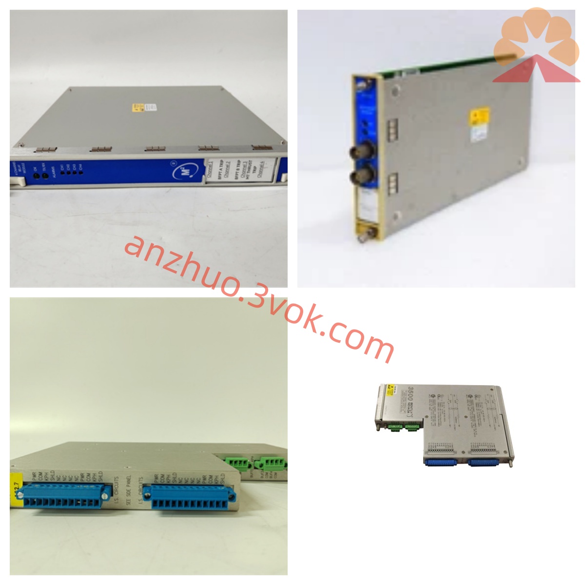
Description
Technical Specifications
The power is uniformly supplied by the chassis backplane, and the standard full-height card installation structure is adopted.
Four independent acquisition channels, compatible with mainstream specifications of eddy current probes.
The measurement accuracy is stable, and the frequency response is adapted to the routine operating conditions of the unit.
An internal alarm relay is built-in, and 4-20 mA analog signal output is supported.
The working temperature ranges from 0°C to 60°C, and the storage temperature ranges from -40°C to 85°C. It has industrial dust-proof and shock-resistant characteristics.
Installation and Wiring
The module is smoothly inserted into the chassis slot and locked to ensure a tight bus contact.
The sensing lines are connected to the corresponding ports according to the channel number, and are separated from the power cables for wiring.
The alarm lines and signal output lines are properly connected, and the connection terminals are stable without loose connections.
After the overall layout is completed and verified to be error-free, power is applied to conduct parameter debugging.
Maintenance and Care
Regularly check the operation status of the indicator lights and monitor the values to ensure they remain stable without sudden changes.
Regularly tighten the connection terminals, check the appearance and cleanliness of the cables.
Regularly calibrate the measurement accuracy and test the sensitivity of the alarm trigger action.
Avoid damaging the interface by frequently plugging and unplugging, and store the idle components in a dry environment. Fault diagnosis
There is no data display in the channel. Check the power supply, slot contact, and sensor circuit continuity.
The numerical fluctuations have significant deviations. Adjust the installation gap of the probe and improve the shielding grounding treatment.
The alarm start and stop are abnormal. Verify the set threshold, and test the conduction performance of the relay contacts.
The signal transmission is abnormal. Investigate the wiring status and verify the relevant configuration parameters.
Get a Quote