72311-03-04-04-01-03-15
Description
Technical Specifications
The power is uniformly supplied by the frame backplane, occupying the standard full-height slots of the frame.
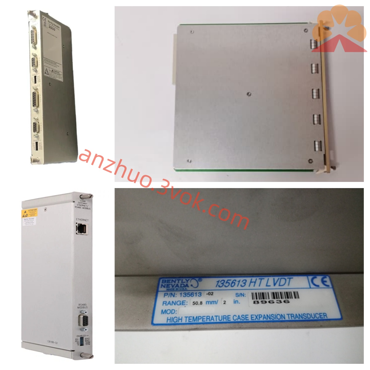
Four independent acquisition channels, compatible with the 3300XL series eddy current probes.
Excellent measurement accuracy, with a range suitable for common displacement and expansion monitoring conditions in the field.
Built-in relay alarm output, equipped with a communication interface to achieve remote data transmission.
Operating temperature range: 0°C to 60°C, storage temperature range: -40°C to 85°C. It has dust-proof and shock-resistant industrial compatibility.
Installation and wiring
Align the card slot with the slot and insert it smoothly into the frame, locking the latch to ensure stable contact of the backplane bus.
Connect the sensing lines to the corresponding ports according to the channel number, and separate them from the power cables to reduce interference.
Connect the alarm control lines and communication lines to the corresponding terminals in accordance with regulations, ensuring firm wiring without loose or incorrect connections.
After the installation and wiring are completed, conduct a comprehensive check to confirm there are no errors before powering on for debugging and operation.
Maintenance and care
Regularly observe the status of the panel indicator lights, monitor the values to ensure they are stable without abnormal fluctuations.
Regularly tighten the connection terminals, check for any damage, aging, or accumulation of dirt on the cables.
Periodically calibrate the measurement accuracy and verify the sensitivity and effectiveness of the alarm trigger action.
Reduce unnecessary plug-and-unplug operations on the protective interface and store idle devices in a dry and ventilated environment. Fault diagnosis
The channel has no data output. Check the power supply, slot contact, and sensor circuit continuity in sequence.
The numerical fluctuations have a significant deviation. Adjust the probe installation gap and optimize the shielding and grounding configuration of the lines.
The alarm action is abnormal. Verify the threshold setting parameters and test the contact performance of the relay.
Communication transmission failure. Investigate the line connection status and verify the communication port and protocol parameters.
Get a Quote