72564-01-04-03-04-01-01-11
Description
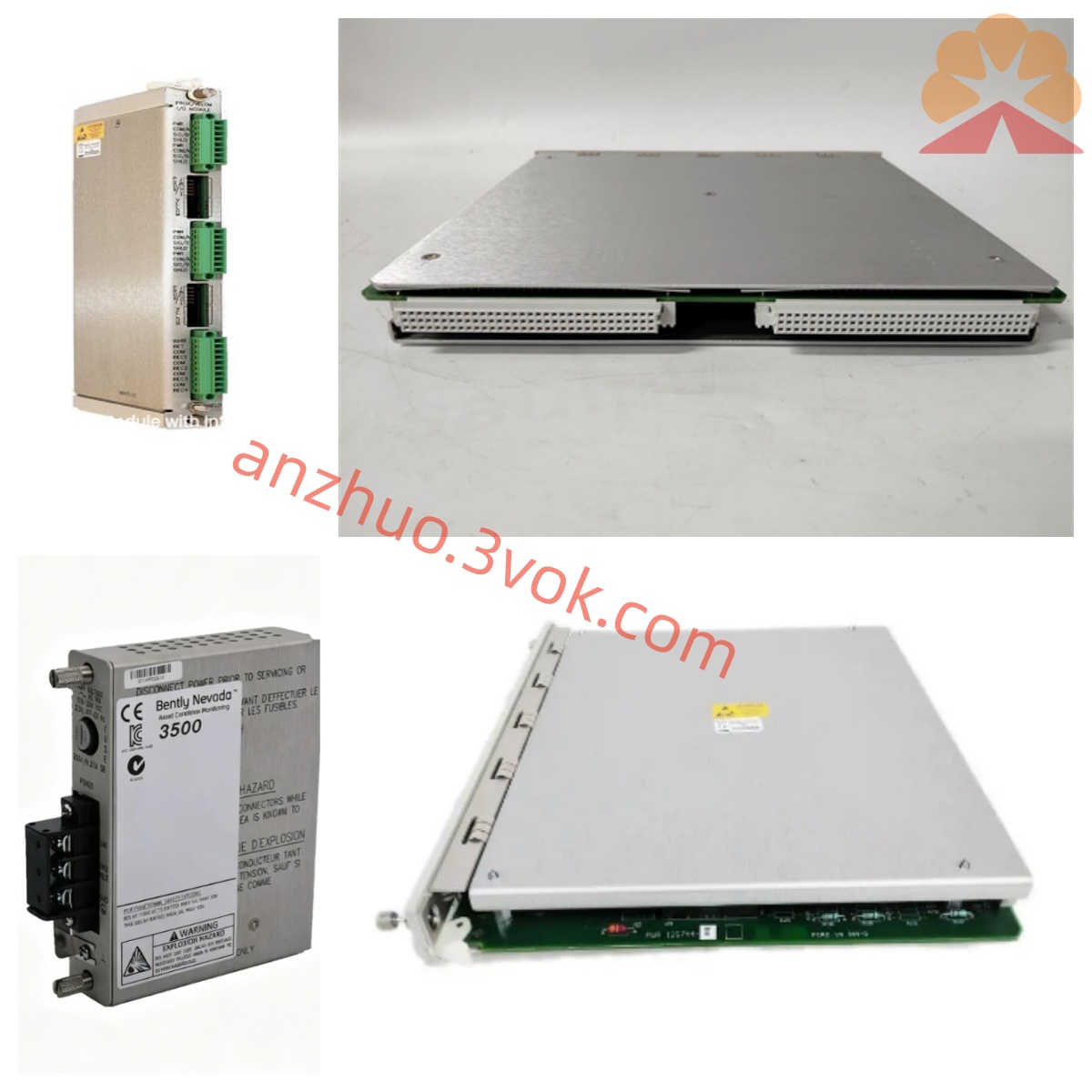
Technical Specifications
Using -24VDC direct current power supply, the normal voltage range is -17.5VDC to -26VDC.
Compatible with magnetic-electric induction speed probes, covering the normal operating speed range of conventional units.
The measurement accuracy is stable, with a standard 4-20mA analog output, and an integrated alarm relay contact.
Installed using cabinet rail mounting, suitable for industrial site conditions.
Operating temperature: -20℃ to 60℃, storage temperature: -40℃ to 85℃. It has dust-proof and shock-proof protection capabilities.
Installation and wiring
The module is fixed with a snap-fit on the standard cabinet rail. The installation position should be away from strong electromagnetic interference equipment such as motors and frequency converters.
The sensing cable and power cable are laid separately to reduce signal interference.
Connect the power supply line according to specifications and firmly connect the system ground wire. The wiring of the speed sensor should correspond to the signal port.
The analog output terminal is connected to the central control acquisition device, and the alarm contact is connected to the on-site interlock circuit.
After wiring, check the connection status of the lines, confirm there are no incorrect connections or loose connections, and then power on for debugging.
Maintenance and care
Daily inspection of the appearance integrity of the module, maintaining a clean surface without rust or stains, observing that the speed indication is stable without abnormal fluctuations.
Regularly tighten the wiring terminals and check if the cables are damaged or aged.
Timely test the power supply voltage value, verify the accuracy of speed measurement, and test the effectiveness of alarm interlock actions.
Do not disassemble the sensor circuitry while powered on, to avoid incorrect wiring and damage to internal components.
Idle equipment should be placed in a dry and ventilated environment, stored in a dust-proof and moisture-proof manner. Fault diagnosis
When the rotational speed is not displayed, systematically check the power supply connection and disconnection, the sensor circuit connection and continuity, and the correctness of wiring. Replace the faulty parts to locate the fault.
If the rotational speed fluctuates with a large deviation, investigate the electromagnetic interference factors, check the stability of the sensor installation, and verify the shielding and grounding effect of the lines.
If the alarm is triggered abnormally, check the internal rotational speed threshold parameters, test the contact point connection status of the relay, reset the parameters if they are abnormal, and replace the faulty hardware components in time if there is a hardware failure.
Get a Quote