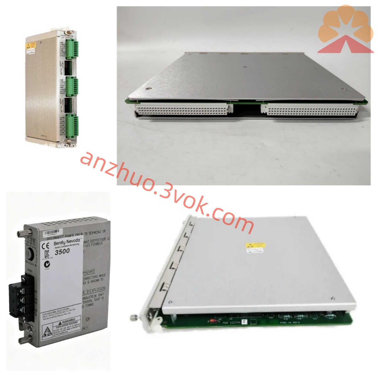
72601-22-01-05-01-01-03-00-01
Description
II. Technical Specifications
Electrical Parameters
Power Supply: -17.5 to -26VDC (standard - 24VDC)
Power Consumption: ≤ 180mA
Input: 2 electrical eddy current probes (5/8/11/14mm), sensitivity 7.874V/mm
Measurement Range:
Vibration: 0–250μm (0–10mil)
Displacement: ±1mm (±40mil)
Accuracy: ±1% FS (full scale)
Output: 4–20mA (load ≤ 500Ω), 0–10V optional
Alarm: 2 relays (normally open / normally closed, 24VDC/1A)
Environmental and Mechanical
Installation: Standard DIN rail (compatible with 7200 cabinet)
Size: Approximately 120×45×85mm
Weight: Approximately 0.5kg
Operating Temperature: -20℃ to +60℃
Storage Temperature: -40℃ to +85℃
Humidity: 5%–95% (no condensation)
Protection: IP30
III. Installation and Wiring Installation Requirements
Insert the device into the DIN rail of the cabinet and secure it. Keep it away from strong interference sources such as frequency converters and motors (distance ≥ 300mm).
Separate the wiring for the sensor, power supply, and output lines. Ground the shield layer at one end.
Terminal block (front side) Table
Terminal Function
PWR- Positive pole of -24VDC
PWR+ Negative pole of -24VDC
GND System ground
CH1/P Positive pole of channel 1 probe
CH1/N Negative pole of channel 1 probe
CH2/P Positive pole of channel 2 probe
CH2/N Negative pole of channel 2 probe
OUT+/- 4–20mA output
ALM1/ALM2 Alarm relay contacts
Wiring steps
Power supply: -24VDC connected to PWR±, GND connected to system ground (ground resistance < 4Ω).
Probe: CH1/CH2 connected to two electrical eddy current probes (distinguish positive and negative poles).
Output: 4–20mA connected to DCS/PLC analog input.
Alarm: ALM contacts connected to external alarm / shutdown circuit.
Check: After correct wiring and insulation > 1MΩ, power on.
V. Maintenance and Care
Daily inspection (every shift)
Appearance: No oil stains, corrosion, clear display, normal power / alarm indicator lights.
Values: Stable measurement, no jumps, matching with on-site conditions.
Wiring: Terminal tightened, cable without damage, good shielding.
Regular maintenance
Weekly: Clean the panel dust, check the guide rail fixation.
Monthly: Verify power supply (-24VDC ± 1V), check the consistency of measurement values with the probe.
Every six months: Calibrate 4–20mA output, test the reliability of alarm / shutdown actions.
Annually: Coordinate with the overall calibration of the probe, calibrate or replace the module if the error exceeds ±1% FS.
Prohibited
Do not plug or unplug the probe / cable while powered on to avoid damage to the input circuit.
Do not connect the probe with excessive range or reverse polarity.
Avoid water ingress, oil ingress, strengthen protection in humid environments.
VI. Fault Diagnosis
1. No display / display "Err"
Reason: Power failure, probe disconnection / short circuit, wiring error, module failure.
Troubleshooting:
Test -24VDC to see if it is normal.
Use a multimeter to check the probe connection, wiring correctness.
Replace a known intact probe, still abnormal then module damaged.
2. Jumping values / large drift
Reason: Electromagnetic interference, probe loosening, shielding damage, poor grounding.
Troubleshooting:
Move away from interference sources, re-arrange the wiring.
Tighten the probe installation, check the single-ended grounding of the shielding layer.
Check the grounding resistance < 4Ω.
3. False alarm / no alarm trigger
Reason: Threshold setting error, relay contact oxidation, module failure.
Troubleshooting:
Check the high alarm / dangerous threshold (such as vibration high alarm 120μm, dangerous 200μm).
Manually trigger the alarm, test the contact connection is normal.
Re-calibrate the alarm logic, if ineffective, replace the module.
Get a Quote