
Description
PEPPERL+FUCHS KFD2-UT2-EX1: Universal Temperature Converter Isolated Barrier Product Description
Brand and Product Identification
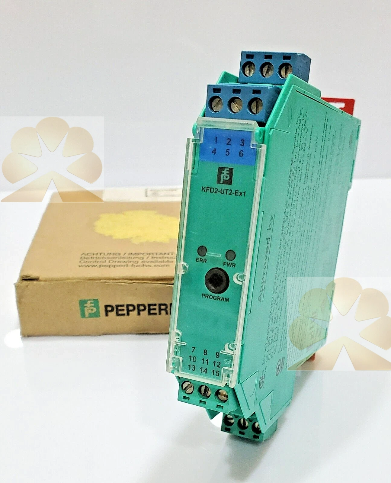
The PEPPERL+FUCHS KFD2-UT2-EX1 is a one-channel isolated barrier and universal temperature converter from the Pepperl+Fuchs K-System. The KFD2-UT2-Ex1 model receives temperature or resistive sensor signals from a hazardous area and converts them to a proportional current output for the safe-area control system. It combines intrinsic safety isolation, signal conditioning, sensor fault detection and digital configuration in a single DIN-rail mounted interface module. A related KFD2-UT2-Ex1-1 version provides voltage output instead of current output; the base KFD2-UT2-Ex1 described here is the current-output version.
Product Function and System Role
The KFD2-UT2-Ex1 is used for intrinsic safety temperature measurement applications. It connects resistance temperature detectors, thermocouples, potentiometers or voltage sources in the hazardous area and transmits a proportional analog current signal to a PLC analog input, display or process controller in the safe area. The module provides galvanic isolation between the hazardous-area sensor circuit and the safe-area control circuit, while conditioning the sensor signal and detecting sensor or wiring faults. It can also be configured as a signal splitter for applications requiring multiple signal paths.
Supply and Power Specifications
The module is supplied at 24 V DC through the Power Rail or terminals 14+ and 15-. Rated voltage Ur is 20 to 30 V DC. Power dissipation and power consumption are each less than or equal to 0.98 W. The output and programming input have functional insulation with a rated insulation voltage of 50 V AC. There is no electrical isolation between the programming input and the supply; the programming cable provides galvanic isolation to avoid ground loops during configuration.
Sensor Input Types
The KFD2-UT2-Ex1 accepts RTD, thermocouple, potentiometer and voltage inputs on terminals 1, 2, 3 and 4. RTD types include Pt10, Pt50, Pt100, Pt500 and Pt1000 to EN 60751, GOST platinum types, Cu10, Cu50, Cu100 and Ni100. RTD measuring current is approximately 200 µA, and 2-wire, 3-wire or 4-wire RTD connection is supported. Thermocouple types include B, E, J, K, N, R, S and T to IEC 584-1, type L to DIN 43710, and TXK, TXKH and TXA types. Cold junction compensation can be external or internal. A removable K-CJC terminal block is available as an accessory for internal thermocouple cold junction compensation.
Additional Input Specifications
The potentiometer input supports 0 to 20 kΩ in a 2-wire connection and 0.8 to 20 kΩ in a 3-wire connection. The voltage input is selectable within minus 100 to plus 100 mV. Input resistance for the mV range is 1 MΩ or higher. Measurement loop monitoring detects sensor breakage and sensor short circuit. Input response time varies by sensor type: approximately 1 s for mV signals, 1.1 s for thermocouples with cold junction compensation or fixed reference temperature, 920 ms for 3-wire or 4-wire RTD, 800 ms for 2-wire RTD, and 2.05 s for potentiometer input.
Output and Fault Signaling
The analog current output is selectable for 0 to 20 mA or 4 to 20 mA. Output terminals depend on source or sink mode: terminal 7 is source negative or sink positive, terminal 8 is source positive, and terminal 9 is sink negative. In source mode, load is 0 to 550 Ω with open-circuit voltage of 18 V or less. In sink mode, voltage across terminals is 5 to 30 V; if the source voltage exceeds 16.5 V, a series resistance must be added according to the datasheet formula. Fault signals follow NAMUR NE43: downscale 0 or 2 mA, or upscale 21.5 mA. Faults are indicated by LEDs according to NAMUR NE44 and a separate collective error message output.
Configuration and Diagnostics
The KFD2-UT2-Ex1 is configured using PACTware configuration software. Configuration parameters include sensor type, measuring range, output range, source or sink mode, fault behavior and monitoring functions. The diagnostic functions provide sensor breakage detection, sensor short-circuit detection and line fault detection for the connected temperature element or wiring. LED indications support local commissioning and maintenance, while the collective error output provides remote fault indication to the control system.
Intrinsic Safety and Functional Safety
The input is certified Ex ia under EU-type examination certificate CESI 04 ATEX 143. Input intrinsic safety parameters are Uo 9 V, Io 22 mA and Po 50 mW. Maximum safe voltage is 250 V, noting that this is not the rated voltage. Input and other circuits provide safe electrical isolation according to IEC/EN 60079-11, with a voltage peak value of 375 V. The module is suitable up to SIL 2 according to IEC 61508 and IEC 61511. Functional safety suitability must be verified within the overall safety loop and according to the device-specific safety documentation.
Mechanical and Environmental Data
The KFD2-UT2-Ex1 housing is K-System type B2, with dimensions of 20 mm width, 119 mm height and 115 mm depth, and a mass of approximately 130 g. Degree of protection is IP20. Ambient operating temperature ranges from minus 20 to plus 60 degrees Celsius. The module mounts on a standard DIN rail in the control cabinet or interface rack, with hazardous-area sensor terminals and safe-area output terminals separated according to the wiring diagram.
Typical Application Scenarios
Typical applications include temperature measurement in oil and gas, chemical, petrochemical, pharmaceutical, power, water treatment and process industries with classified hazardous areas. The module connects RTDs, thermocouples or potentiometric sensors to a PLC or DCS analog input while maintaining intrinsic safety. Common signals include reactor or vessel temperature, pipe temperature, bearing temperature, oven or furnace temperature, process air or gas temperature, and position feedback from potentiometric sensors in hazardous locations.
Installation and Commissioning Notes
Installation should follow the Pepperl+Fuchs K-System manual, intrinsic safety wiring regulations and local electrical codes. Verify sensor type, wiring convention, terminal assignment, output range, source or sink mode, fault behavior and supply voltage before configuration. Connect the hazardous-area sensor to terminals 1 to 4 and the safe-area current output to the designated output terminals. Use the PACTware software to set the sensor and output parameters, and verify fault detection by simulating sensor breakage or short circuit during commissioning. Cable parameters must remain within the certified intrinsic safety limits, and grounding and shielding should follow the site intrinsic safety practice.
Advantages and Selection Notes
The KFD2-UT2-Ex1 offers universal RTD, thermocouple, potentiometer and mV input, current output, source or sink mode, intrinsic safety isolation, sensor and line fault diagnostics, PACTware configuration, SIL 2 suitability and compact K-System DIN-rail mounting. When selecting a converter, distinguish the current-output KFD2-UT2-Ex1 from the voltage-output KFD2-UT2-Ex1-1, confirm sensor type and range, verify approval and entity parameters, and check safety loop requirements. The module is an isolated temperature signal converter, not a temperature controller, transmitter, display, safety relay or field sensor; its role is to condition and isolate a hazardous-area temperature sensor signal for the safe-area control system.
Get a Quote