
Description
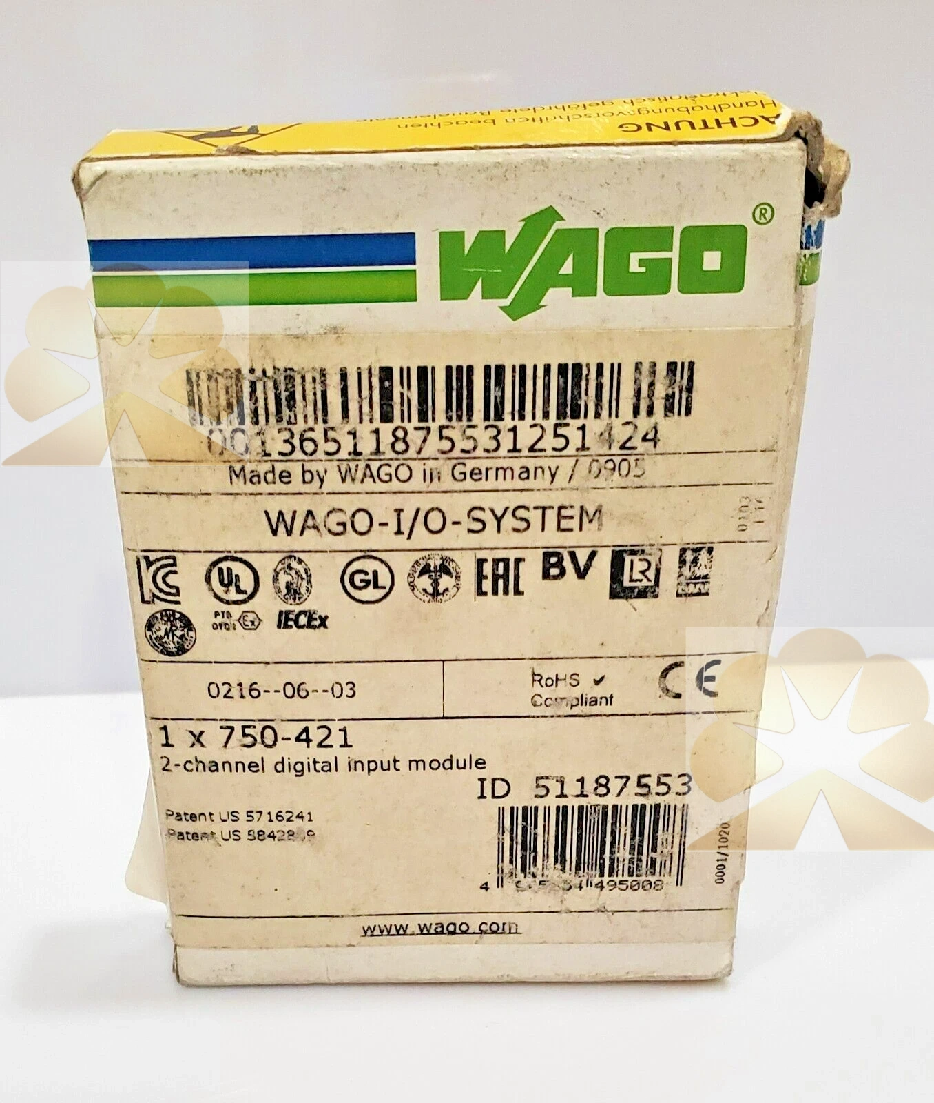
WAGO 750-421: 2-Channel Digital Input Module Product Description
Brand and Product Identification
The WAGO 750-421 is a two-channel digital input module from the WAGO I/O System 750/753 family. The item number 750-421 identifies a 24 V DC digital input module with a 3 ms input filter, two- to three-wire sensor connection, high-side switching and channel diagnostics. The module receives binary control signals from field sensors or switches and provides short-circuit-protected sensor supply voltage per channel. It operates on all head stations of the WAGO I/O System 750/753 and transfers input status and diagnostic information through the fieldbus coupler to the higher-level controller.
Product Function and System Role
The 750-421 digital input module interfaces field-side binary devices such as proximity switches, pushbuttons, limit switches, photoelectric sensors and two- or three-wire sensors to the PLC or industrial controller. It converts field switch or sensor signals into digital process image bits that the controller can read. The module also supplies sensor power per channel and monitors the sensor supply for short circuits to ground, reporting the fault through status LEDs and process image diagnostic bits.
Input Specifications and Signal Levels
The module provides two digital input channels. The sensor connection supports two channels, each compatible with two-wire or three-wire sensors. The digital input filter is an RC noise-rejection filter with a 3.0 ms time constant. Input current per channel for a one signal is typically 3.7 mA. The zero-signal voltage range is minus 3 to plus 5 V DC, and the one-signal voltage range is 15 to 30 V DC. Inputs provide high-side switching, and the sensor supply is 24 V DC.
Power Supply and Isolation
The module system supply is 5 V DC through data contacts. The field supply is 24 V DC within minus 25 to plus 30 percent, supplied through power jumper contacts; field-side supply voltage is transmitted via the spring contact, while power supply enters through the blade contact. Isolation between system and field side is 500 V. The module has two incoming power jumper contacts, and eight CAGE CLAMP connections for the inputs.
Terminal Assignment
Channel 1 uses terminal 1 for DI 1 signal voltage, terminal 2 for 24 V field supply voltage, terminal 3 for DI 1 field supply 0 V, and terminal 4 for Uv1 sensor supply. Channel 2 uses terminal 5 for DI 2 signal voltage, terminal 6 for 24 V field supply voltage, terminal 7 for DI 2 field supply 0 V, and terminal 8 for Uv2 sensor supply. The power jumper contacts distribute field power to adjacent modules, while data contacts carry the bus communication within the I/O station.
Diagnostic Functions and Process Image
Each channel has an independent sensor supply. For each channel, a green status LED indicates signal status, and a red error LED indicates a short circuit to ground. In the event of a sensor supply short circuit, a channel-specific error bit is set in the input process image: bit 2 for channel 1 and bit 3 for channel 2. After the error is corrected, the diagnostic indication remains for 100 ms as pulse extension, and the error is acknowledged automatically after rectification. The input process image maps DI 1 to bit 0, DI 2 to bit 1, channel 1 short circuit to bit 2, and channel 2 short circuit to bit 3.
Mechanical Construction and Materials
The 750-421 housing is light gray, made of polycarbonate and polyamide 6.6, with a fire load of 1.316 MJ. Module weight is 49.8 g. The module uses WAGO CAGE CLAMP spring connection technology and power jumper contacts for field supply distribution. A slot for an optional Mini-WSB marking accessory is provided on the module. The module clips into the WAGO 750/753 I/O station alongside couplers, power supply modules and other input or output modules.
Typical Application Scenarios
Typical applications include digital sensing in machine automation, conveyor systems, packaging machines, assembly lines, material handling, process equipment, HVAC controls and general PLC I/O expansion. The module is suitable for discrete feedback such as running or stopped status, limit position detection, presence or absence sensing, valve position feedback, pushbutton or selector switch input, and sensor contact monitoring in 24 V DC control systems.
Installation and Wiring Notes
Installation and commissioning should follow the WAGO I/O System 750/753 system manual and module documentation. Mount the module in the I/O station, connect field sensors to the assigned DI and sensor supply terminals, and distribute field power through the jumper contacts. Observe high-side switching configuration, sensor wire type, shielding and separation between field and system wiring. Verify process image bit assignment, LED status and diagnostic behavior after wiring. Power should be removed before inserting or removing modules or changing jumper wiring, and ESD precautions should be observed.
Advantages and Selection Notes
The 750-421 offers two 24 V DC digital inputs, per-channel sensor supply, 3 ms noise filtering, high-side switching, channel short-circuit diagnostics, CAGE CLAMP connections, 500 V system-field isolation and compatibility with the WAGO 750/753 I/O system. When selecting an input module, confirm sensor type, wiring convention, signal voltage, required channel count, diagnostic needs and PLC or coupler compatibility. The 750-421 is a digital input interface module, not a sensor, actuator, power supply, controller or output relay; its role is to read binary field signals and report their status to the control system.
Get a Quote