
Description
已思考
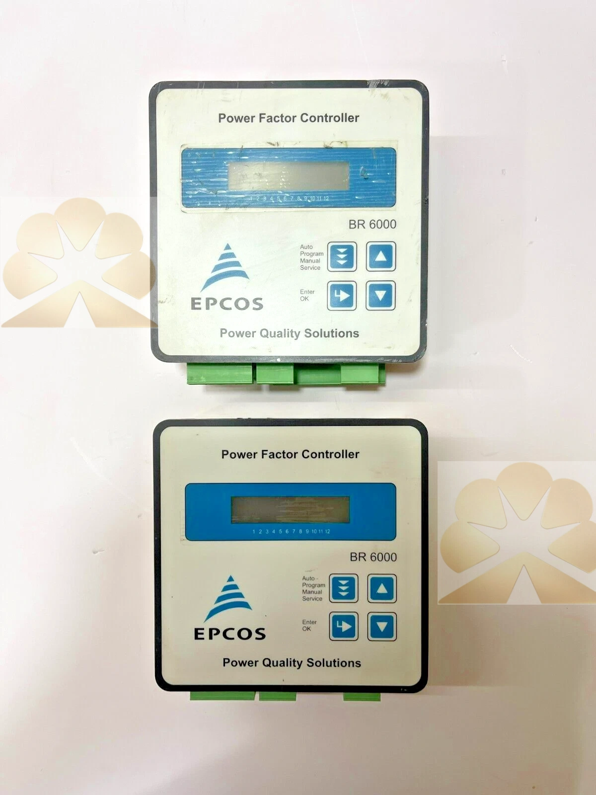
EPCOS BR6000-R12/S485 B44066-R6412-R230: BR6000 Power Factor Controller Product Description
Brand and Product Identification
The EPCOS BR6000-R12/S485, ordering code B44066-R6412-R230 or B44066R6412E230, is an intelligent power factor correction controller from the EPCOS BR6000 series, now associated with TDK Electronics EPCOS. The model BR6000-R12 identifies a 12-relay-output controller, and the S485 suffix identifies the RS485 communication interface. The ordering code B44066-R6412-R230 corresponds to the 12-step relay-output BR6000-R12 with RS485 and a 230 V supply configuration. The device is a panel-mounted power factor regulator used to switch capacitor steps in automatic reactive power compensation systems.
Product Function and System Role
The BR6000-R12/S485 controller measures mains voltage and current, calculates power factor, active power, reactive power, apparent power and related system values, and switches capacitor contactors in steps to maintain the target cosine phi. It provides automatic power factor correction for low-voltage electrical installations, reducing inductive reactive power drawn from the supply, improving load factor and lowering unnecessary energy losses. The controller is installed in a capacitor bank or distribution panel and controls up to twelve compensation stages.
Control Outputs and Communication
The R12 version provides twelve relay outputs for switching capacitor contactors. Relay switching voltage is a maximum of 250 V AC, switching power is a maximum of 1000 W, and maximum switching frequency is 0.25 Hz. Expected mechanical relay life exceeds 30 million switching operations, and expected electrical life exceeds 5 million switching operations at a 200 VA load with cosine phi 0.4. The S485 version includes an RS485 interface for connection to a supervisory or monitoring system. Related BR6000 versions may offer transistor outputs for thyristor switching, but the R12 relay version is designed for contactor-switched capacitor stages.
Supply and Measurement Specifications
The controller supply voltage is 230 V AC for the R230 configuration, with other voltages available on request. Mains frequency is 50 and 60 Hz, and power consumption is 5 VA. The measurement voltage range is 30 to 300 V AC phase to neutral, equivalent to 50 to 525 V phase to phase. Measurement current can use x/1 A or x/5 A current transformer secondaries. Minimum operating current is 40 mA, and maximum current is 5.3 A sinusoidal. Zero voltage release occurs within less than 15 ms. The target cosine phi range is 0.8 inductive to 0.8 capacitive.
Control Modes and Operating Features
The BR6000 supports series switching in LIFO order, circular switching in FIFO order, and a self-optimized intelligent control mode. It provides twenty preset control series plus a control series editor for free programming. Switching time and discharge time ranges are each 1 to 1200 seconds. The controller supports four-quadrant operation, which is useful for standby generator applications and systems that may export reactive power. Intelligent control capability allows the regulator to adapt stage switching to changing load conditions.
Display and Alarm Functions
The controller uses a large multifunctional LCD with two by sixteen characters, graphic and alphanumeric display and LCD illumination. The display shows system voltage, reactive power, active power, apparent power, apparent current, temperature, real-time cosine phi, target cosine phi and kvar value to target. The alarm output is a potential-free contact with six selectable parameters. Alarm conditions include insufficient compensation, over-compensation, under-current, over-current, over-temperature and harmonics exceeded. Recorded values can be recalled, including number of contactor switching operations, maximum voltage, maximum reactive power, maximum active power, maximum apparent power and maximum temperature.
Mechanical Construction and Environmental Ratings
The BR6000 is a panel-mounted instrument with a housing size of 144 by 144 by 60 mm and a weight of 1 kg. The front plate is IP54 according to IEC 529 and DIN 40050, while the rear side is IP20. Operating temperature ranges from minus 10 to plus 60 degrees Celsius, and storage temperature ranges from minus 20 to plus 65 degrees Celsius. Mounting position may be any orientation. Operating height is 0 to 3000 m above sea level, and humidity class is 15 to 95 percent without dew. The device is overvoltage class III and pollution degree 2.
Typical Application Scenarios
The BR6000-R12/S485 is used in automatic power factor correction panels for industrial plants, commercial buildings, manufacturing lines, workshops, compressor and motor loads, and installations with multiple capacitor stages. It suits low-voltage distribution systems where reactive power compensation is required to maintain power factor at the utility or plant target. The RS485 interface supports integration with building energy management, SCADA or power quality monitoring systems. Common loads include induction motors, transformers, welders, pumps, fans, compressors and mixed commercial-industrial supplies.
Installation and Commissioning Notes
Installation should follow the EPCOS BR6000 operating manual and local electrical codes. The controller is mounted in the panel cutout, with supply voltage, current transformer inputs, voltage measurement wiring, relay output contacts and RS485 communication connected according to the rear wiring diagram. During commissioning, set the system voltage, CT primary and secondary ratings, number of outputs, control mode, target cosine phi, step kvar values and control series according to the capacitor bank and load. Current transformer polarity and phase assignment must be verified, and alarm parameters should be configured to match the installation. Maintenance consists of checking display readings, alarm status, relay operation, CT wiring and communication status.
Advantages and Selection Notes
The BR6000-R12/S485 offers twelve relay outputs, RS485 monitoring, self-optimizing control, multiple control modes, four-quadrant operation, extensive measurement and alarm functions, recorded value recall and a standard 144 by 144 mm panel enclosure. When selecting a replacement, confirm supply voltage, number of stages, relay or transistor output type, communication interface, CT ratio and measurement voltage. The controller is a power factor regulator for capacitor bank control, not a capacitor, contactor, motor starter, power supply or energy meter by itself; its role is to measure reactive power and switch compensation stages automatically.
Get a Quote