
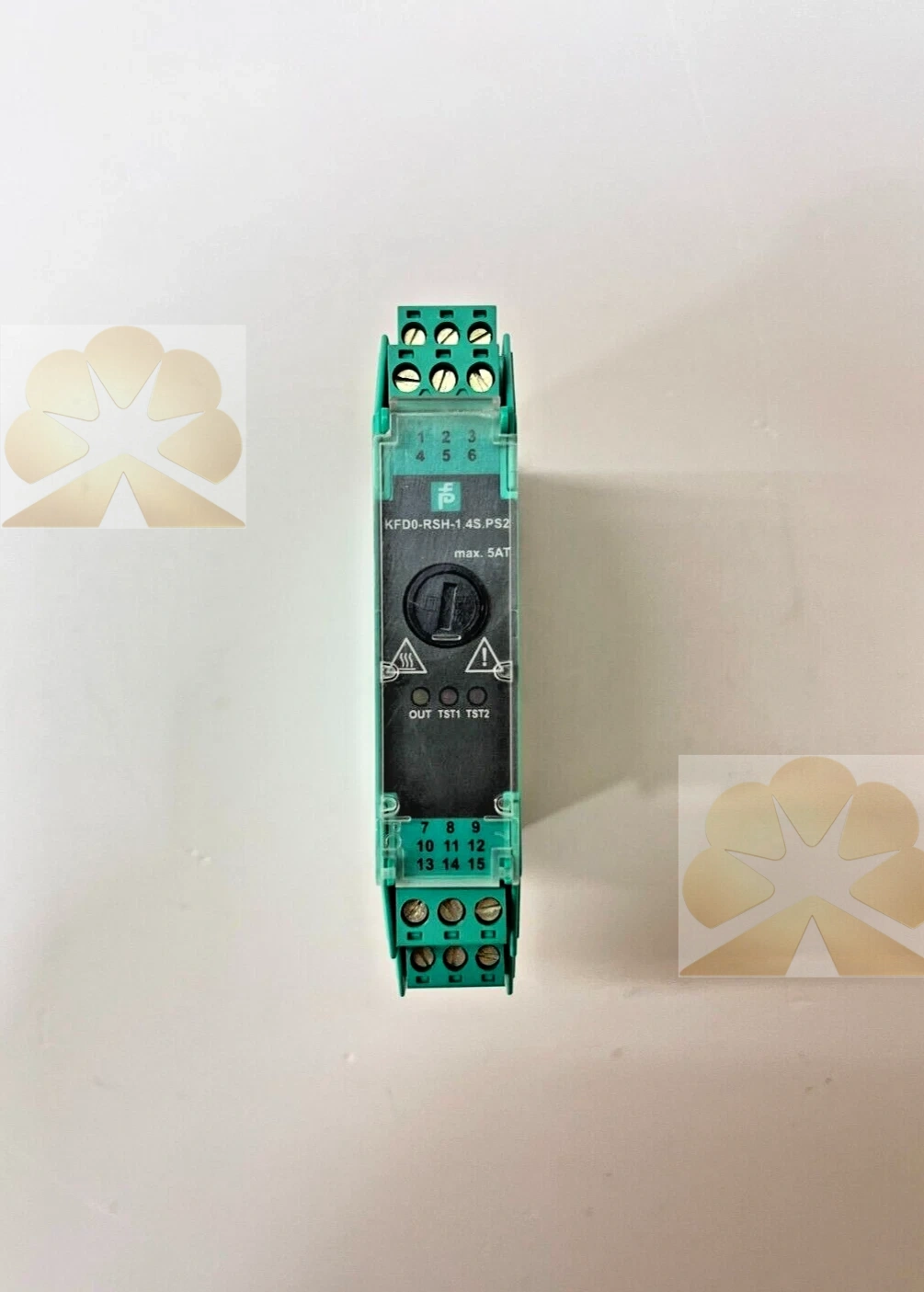
Description
PEPPERL+FUCHS KFD0-RSH-1.4S.PS2: K-System Safety Relay Module Product Description
Brand and Product Identification
The PEPPERL+FUCHS KFD0-RSH-1.4S.PS2 is a one-channel signal conditioner relay module from the Pepperl+Fuchs K-System DIN-rail mounted interface family. The model code identifies a safety relay module with a loop-powered 24 V DC supply, a non-polarized logic input, fail-safe relay contact outputs, test pulse immunity and functional safety certification up to SIL 3 according to IEC/EN 61508. The module is designed for safely switching load circuits in process automation and Safety Instrumented System applications where control-side logic must drive a separated relay output.
Product Function and System Role
The KFD0-RSH-1.4S.PS2 relay module isolates load circuits up to 230 V from the 24 V DC control interface. It receives a logic-level control signal on the input side and switches relay contacts on the output side according to the selected safe function. The module serves as an interface between a safety controller, PLC output or trip logic and an external load such as a solenoid valve, contactor coil, indicator or alarm circuit. Galvanic isolation separates the control-side logic from the switched load, reducing interference and protecting the control system from load-side faults.
Supply and Input Specifications
The module is loop powered at 24 V DC. The 0-signal input level is minus 3 to 3 V DC, and the 1-signal input level is 20 to 26.5 V DC. The logic input is non-polarized, so it can accept the control signal without observing a fixed polarity on the input terminals. Rated input current is 45 to 50 mA, and power consumption is below 1.5 W. Input terminals are terminals 7 and 8, while test input terminals are terminals 10, 11 and 12.
Output Relay Functions
The relay module provides output I and output II with different safety functions. Output I supports the energized to safe function, abbreviated ETS, and is permitted for SIL 3 applications on that output. Output II supports the de-energized to safe function, abbreviated DTS, and is permitted for SIL 3 applications on that output. A dual-pole switching function, abbreviated DPS, can be implemented by combining output I and output II. Output I terminals are 2 and 3, output II terminals are 4, 5 and 6, and combined DPS outputs use terminals 2, 3, 4, 5 and 6.
Contact Ratings and Protection
The relay contact loading is rated for 253 V AC at 5 A with cosine phi 0.7, and 30 V DC at 5 A for resistive load. Minimum switch current is 2 mA at 24 V DC. Output II is protected against contact welding by a fuse, depending on the terminal used. The fuse rating is 2.5 A, maximum 5 A, and the recommended maximum utilization of the fuse is 80 percent. The relays are of diverse design but have a common effect on the individual switch output, supporting diagnostic checking of the relay state.
Test Function and Diagnostics
Relay checking is performed through terminals 10, 11 and 12. The test mode is indicated by LEDs according to NAMUR NE44. The module is immune to test pulses, which helps avoid false switching during routine diagnostics or test cycles in a safety loop. The diagnostic and test provisions support proof testing of the Safety Instrumented Function and allow maintenance personnel to verify relay contact state without disconnecting the load circuit.
Functional Safety and Certification
The KFD0-RSH-1.4S.PS2 is assessed for use up to SIL 3 according to IEC/EN 61508. The ETS function is permitted for SIL 3 with output I, and the DTS function is permitted for SIL 3 with output II. The device-specific functional safety manual describes proof test procedures, parameters and installation requirements for use in a Safety Instrumented Function. Certification documentation, including the associated certificate and conformity declaration, should be consulted to confirm the approved architecture, proof test interval and failure data for the specific application.
Explosion Protection and Approvals
The module is a K-System interface product intended for process automation installation. Related German operating documentation identifies an ATEX marking of II 3G Ex nA nC IIC T4 Gc for equipment installed in Zone 2, with certificate PF 15 CERT 3844 X. The device must be installed according to the applicable certificate, instruction manual and local hazardous-area regulations. Exact approval scope, temperature class and zone rating should be verified from the current Pepperl+Fuchs datasheet and certificate rather than assumed from the model code alone.
Mechanical Construction and Wiring
The KFD0-RSH-1.4S.PS2 housing is a compact DIN-rail mounted K-System module with a stated housing width of 20 mm and one channel. Connection is made with screw terminals on the control and load sides. The module is installed on a standard DIN rail inside a control cabinet or interface rack, with input wiring, test terminals and relay output terminals separated according to the wiring diagram. Cable routing should keep low-voltage control logic and switched load circuits apart, and shielding or separation should follow the site EMC and safety wiring practice.
Typical Application Scenarios
Typical applications include safety relay output interfaces in emergency shutdown systems, Fire and Gas monitoring, burner management, machine safety, process trip loops and PLC-based safety systems. The module is commonly used to switch solenoid valves, safety contactors, alarm relays or indicator loads when the safety controller provides a logic output rather than a high-power relay contact. It suits both de-energized-to-safe and energized-to-safe architectures depending on the selected output and safety design.
Installation and Commissioning Notes
Installation and commissioning must be performed by qualified personnel following the Pepperl+Fuchs KFD0-RSH-1.4S.PS2 operating manual, safety manual and local electrical codes. Before wiring, confirm the selected safety function, ETS, DTS or DPS, and connect the corresponding output terminals. Verify the control signal voltage, input polarity tolerance, load voltage, contact current, fuse rating and isolation requirements against the datasheet. During commissioning, perform the required proof test or functional check using the test terminals and observe LED indications. Safety loop design must consider the module within the overall Safety Instrumented Function; the relay module alone does not constitute a complete safety system.
Advantages and Selection Notes
The KFD0-RSH-1.4S.PS2 offers one-channel relay switching, galvanic isolation, non-polarized input, ETS and DTS output functions, combined DPS capability, relay diagnostic test terminals, test pulse immunity, SIL 3 suitability and a compact 20 mm DIN-rail housing. When selecting a replacement or new module, confirm the safety function, output configuration, load rating, supply voltage, terminal arrangement and applicable certifications. The module is a safety relay signal conditioner, not a safety controller, field sensor, circuit breaker or load feeder; its role is to interface and switch a separated relay output in a safety-related control loop.
Get a Quote