
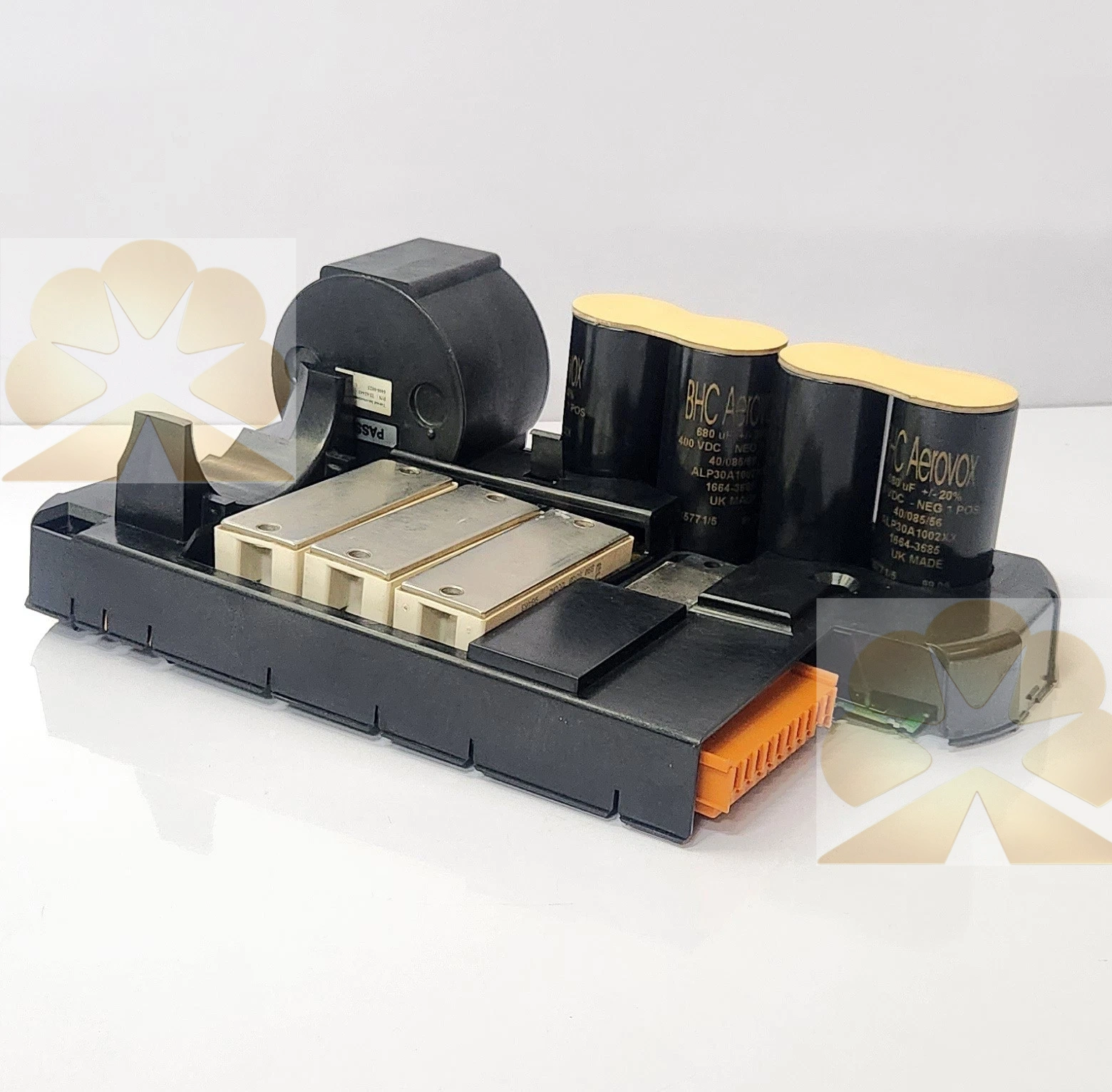
Description
CONTROL TECHNIQUES UD23 ISS 1 S/N:7004-0152
Overview
CONTROL TECHNIQUES UD23 ISS 1, serial trace code 7004-0152, is a power stage board for the legacy Control Techniques Unidrive classic series. This IGBT power board acts as the main inverter section, converting DC bus voltage into three-phase variable-frequency PWM output to drive induction and servo motors. It is widely supplied as exchange spare for Unidrive cabinet overhaul and power board replacement.
Features
CONTROL TECHNIQUES UD23 ISS 1 is matched with the corresponding Unidrive control board and rectifier power supply. It integrates IGBT power devices, gate drive circuits, current sampling and temperature sensing. The current feedback signals are sent back to the control board for closed-loop speed and torque regulation. Built-in protection circuits detect overcurrent, short circuit, DC bus overvoltage, undervoltage and power stage overtemperature.
CONTROL TECHNIQUES UD23 ISS 1 relies on the control board for parameter setting and loop tuning. Onboard fault signals are forwarded to the drive front panel for fault code display. The ISS 1 denotes issue revision 1 of this PCB assembly. This legacy board is designed for continuous industrial operation and is built to withstand switching noise inside drive enclosures.
Specs
CONTROL TECHNIQUES UD23 ISS 1Platform: Control Techniques classic Unidrive Type: Unidrive power stage PCB Model: UD23 Revision: ISS 1 Serial number: 7004-0152 Function: DC to 3-phase PWM inverter, current sampling, IGBT gate driving Protection: overcurrent, short circuit, bus OV/UV, overtemperature Matching system: classic Unidrive drive assembly Mounting: fitted inside Unidrive drive chassis Protection rating: IP20 This is not a control board, encoder or PLC; it is the power inverter board for the original Unidrive drive. CONTROL TECHNIQUES UD23 ISS 1 is widely supplied as service replacement spare for drive power stage failure.
Principle
CONTROL TECHNIQUES UD23 ISS 1 receives stabilized DC bus power from the rectifier module and PWM command signals from the Unidrive control board. The gate drive circuit switches the IGBTs to generate three-phase AC output for the motor. Current transformers and thermistors continuously sample operating conditions. If any limit is exceeded, the board disables the IGBT drive pulses and sends a fault latch signal to the control board.
Applications
CONTROL TECHNIQUES UD23 ISS 1 is deployed for retrofitting legacy Unidrive systems on extruders, winders, conveyors and general process machinery. It is selected for spare inventory and drive cabinet retrofit projects for existing classic Unidrive motion systems.
Get a Quote