Foxboro P0916TP High-Current Field Wiring Termination Base Matching I/A Series FBM242 P0916TA Digital Output Module
Description
3. Complete Product User Manual
User Manual for Foxboro P0916TP Termination Assembly (Matched with FBM242 P0916TA)
1. Basic Product Information
2. Core Technical Specifications
Supported Channel: 16 independent discrete output channels, one-to-one corresponding to FBM242 channels
Field Operating Voltage Range: 15 VDC ~ 60 VDC external load power supply
Single Channel Rated Load Current: Max 2.25 A continuous current; 8 A 20ms inrush current at 30℃
Built-in Protection: Per-channel current limiting, surge suppression, freewheeling diode for inductive loads
Isolation Performance: Group galvanic isolation between field wiring and module bus circuit
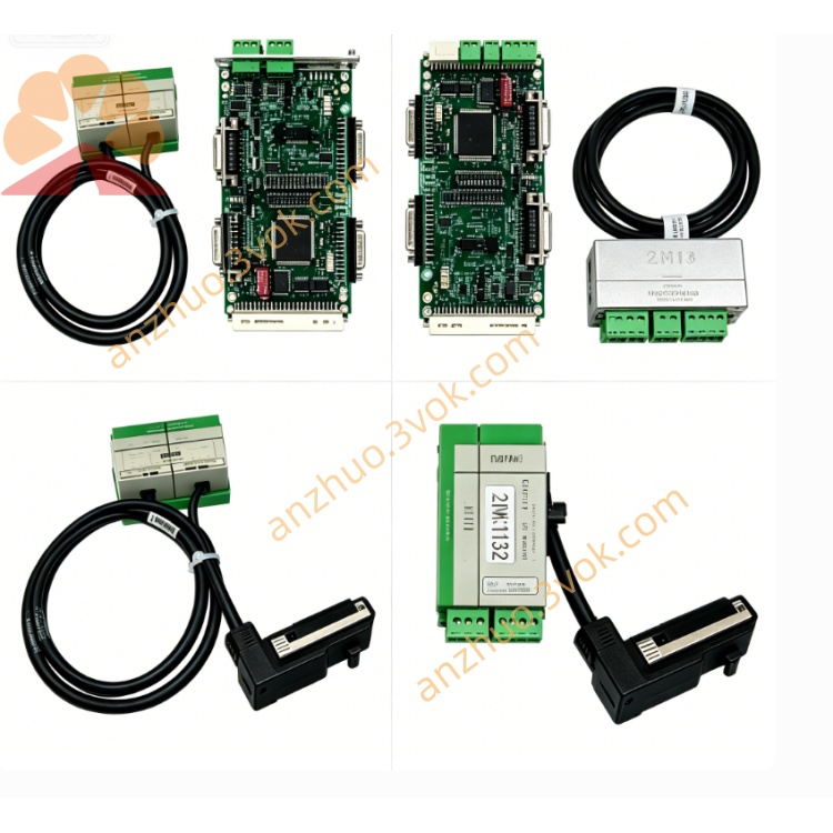
Connection Mode: Special shielded flat cable for signal connection with FBM242 P0916TA
Operating Ambient Temperature: -20℃ ~ +70℃
Storage Temperature: -40℃ ~ +85℃
Ambient Humidity: 0%–95% non-condensing
Anti-Vibration Standard: Compliant with IEC 60068-2-6 industrial vibration test
Overall Dimension: 155mm (L) × 102mm (W) × 48mm (H)
Net Weight: Approx. 0.51kg
Cable Matching: Compatible with Foxboro standard RL4 series termination connection cables
3. Main Product Features
Separated wiring structure: Field heavy-current cables are fixed on P0916TP TA, FBM242 module can be hot-swapped without removing field wiring, greatly cutting maintenance time
Independent screw terminals for each channel, with clear channel number marking to avoid wiring confusion
Integrated surge absorption and inductive load protection circuits, no extra external varistors or diodes required for most solenoid valves and relay loads
Standard DIN rail buckle design, easy installation and disassembly in all standard industrial control cabinets
Flame-retardant high-strength plastic shell, dust-proof, resistant to weak corrosive gas and electromagnetic interference
Full compatibility with all FBM242 series termination cables, baseplates and I/A Series engineering configuration software
Hazardous area compliant design, directly applicable to Class I Div 2 flammable industrial environments without additional explosion-proof accessories
4. Installation & Wiring Operating Instructions
4.1 Installation Steps
Cut off the cabinet 24VDC backplane power and field load power supply before installation to prevent electric shock and short-circuit damage;
Snap the P0916TP onto 35mm DIN rail inside the control cabinet, lock the side buckle to prevent sliding under vibration;
Insert one end of dedicated RL4 flat cable into the rear connector of P0916TP, and plug the other end into the front terminal interface of FBM242 P0916TA module;
Wire on-site solenoid valves, relays, contactors and other load equipment to the corresponding channel screw terminals of P0916TP strictly per official wiring diagram;
Tighten all terminal screws with specified torque, check no loose wiring or bare copper leakage;
Restore cabinet power supply and field load power, confirm FBM module RUN indicator light is steady on with no channel fault alarm.
4.2 Wiring Standard Requirements
Use shielded twisted-pair cables for field load wiring; cable shielding layer single-point grounding at cabinet ground bar;
Do not exceed 2.25A continuous load current per channel to avoid triggering TA built-in overcurrent protection;
Separate heavy-current load wiring and weak-signal control wiring, maintain over 10cm spacing to eliminate signal crosstalk;
For inductive loads such as electromagnetic valves, confirm built-in freewheeling protection circuit of P0916TP is enabled; add external MOV for high-power inductive loads;
All wiring must comply with local electrical codes and hazardous area ATEX installation specifications for explosive sites.
5. Commissioning & Daily Operation Guide
After power-on, check FBM242 module green RUN light keeps on, indicating normal communication between module and P0916TP termination base;
Send switch output commands via DCS upper computer, observe corresponding channel load action to verify correct signal transmission through P0916TP terminals;
If FBM module channel red FAULT light flashes, cut off field load power first, inspect P0916TP terminal short-circuit, overload or reversed wiring;
Complete channel logic test and interlock function verification through I/A Series engineering software;
Perform 72-hour continuous operation test after commissioning to confirm no overheating, false tripping or signal loss on TA terminals.
6. Routine Maintenance & Troubleshooting Guide
6.1 Regular Daily Maintenance
Clean dust on P0916TP terminal surface with dry compressed air every 3 months to prevent poor contact caused by dust accumulation;
Inspect tightness of all wiring terminals and cable connector locking status monthly;
Do not install P0916TP near cabinet heat sources such as transformers, power modules and heaters.
6.2 Common Fault Diagnosis & Solutions
All channels no output signal: Check whether the flat cable between P0916TP and FBM242 is loose or damaged, reinsert or replace the connection cable;
Single channel cannot drive load normally: Check terminal wiring looseness, confirm field load power supply is normal, check TA channel built-in protection circuit tripping;
Frequent channel overcurrent alarm: Reduce single-channel load current, add external current-limiting components for high-power loads;
Terminal local overheating: Retighten loose wiring terminals, replace aging cables with insufficient wire gauge.
7. Safety Warning Clauses
P0916TP is only for indoor sealed industrial control cabinets; outdoor open-air installation is strictly forbidden;
All wiring, disassembly and maintenance operations must be completed by certified automation electricians with power isolation safety measures;
Unauthorized disassembly of the TA shell is prohibited; damage to internal isolation circuits from private disassembly is not covered by official warranty;
When used in Class I Div 2 explosive hazardous areas, all wiring and grounding must strictly follow ATEX Ex nA IIC T4 installation standards;
Discard waste P0916TP termination assemblies in accordance with local electronic waste recycling regulations; random disposal is prohibited.
4. Application Fields (English Version)
- Petroleum & Natural Gas IndustryOffshore oil platforms, natural gas gathering stations, long-distance pipeline control rooms, refinery DCS control systems. P0916TP matches FBM242 to realize wiring transfer for valve switches, pump start-stop and safety interlock discrete signals.
- Petrochemical & Fine Chemical IndustryChemical reaction furnace control, tank farm safety interlock, sewage treatment automation, burner on-off drive signal wiring conversion.
- Thermal & New Energy Power Generation IndustryThermal power plants, biomass power stations, hydropower auxiliary control rooms, substation auxiliary equipment, boiler fans, circulating water pumps and flue gas baffle switch wiring transmission.
- Food & Pharmaceutical Manufacturing IndustryAseptic filling lines, fermentation tank auxiliary equipment, clean workshop safety interlock, sterilization equipment switch signal wiring base.
- Metallurgy & Mineral Processing IndustrySteel rolling lines, mineral separation workshops, smelting furnace auxiliary devices, conveyor belt emergency stop and protection signal wiring.
- Municipal Environmental Protection EngineeringUrban sewage treatment plants, waste incineration power plants, urban water supply pump stations, flue gas desulfurization and denitrification process interlock signal transfer.
- Pulp & Paper Manufacturing IndustryPaper machine actuators, pulp cooking workshop automation, finished product conveying system discrete switch wiring termination.
Information Confirmation & Verification Description
Confirmed fixed information: P0916TP is termination assembly TA matched with FBM242 P0916TA 16-channel discrete output module, I/A Series dedicated wiring base, DIN rail installation, built-in surge and overcurrent protection, Class I Div 2 explosion-proof certification, mainstream industrial application scope, standard TA manual structure.
Content needing further official datasheet verification: Exact maximum wire gauge of terminal ports, full factory original wiring schematic, complete supporting cable model list, customized high-voltage special version parameters.
Get a Quote