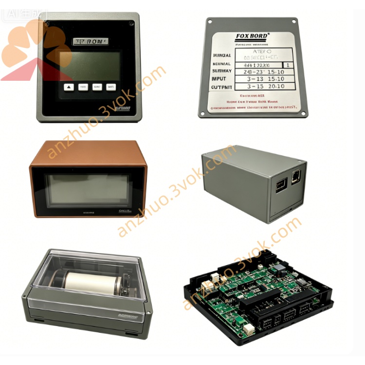
FOXBORO P0916PY I/A Series 16-Channel Modular Expandable Stackable Termination Assembly TA Module
Description
FOXBORO P0916PY Operation Specification Manual
1. Basic Module Information
2. Core Mixed Signal Technical Parameters
Channel Configuration & Signal Compatibility
16 independent signal channels, grouped isolation per 8 channels
Analog signals: 4–20mA, 0–20mA DC current, 1–5VDC HART instrument signals
Discrete input: 15~60VDC dry contact feedback switch signal
Discrete output: 24VDC sink/source digital drive signal, max 0.5A inductive load per single channel
Measurement & Drive Performance
Analog signal basic accuracy: ±0.03% Full Scale
A/D & D/A conversion resolution: 16-bit high precision
Maximum allowable load resistance of analog channel: 500Ω
Isolation & Multi-Layer Protection Circuit
Dielectric isolation voltage between field side and control backplane ≥2500VAC
Analog channel: Current limiting resistors + bidirectional surge absorption filter circuit
Discrete output channel: Built-in freewheeling diodes to eliminate reverse electromotive force of solenoid coils
Each channel independent short-circuit protection with automatic recovery without permanent component damage
Dual-Color LED Fault Diagnostic Indicators
Global operation indicator: Steady green = self-test passed normally; Flashing red = DB25 bus communication fault
Single channel LED: Green = intact normal signal loop; Red = open circuit, short circuit or overload fault
3. Environmental Operating Specifications
4. Installation & Operating Operation Guide
Stackable Module Installation Steps
(1) Install standard 35mm DIN rail horizontally inside large-capacity DCS control cabinet
(2) Snap the first P0916PY module onto DIN rail and lock the bottom anti-slip buckle
(3) Align the upper and lower stacking buckles of additional modules for vertical stacking and interlock fixation
(4) Connect shielded DB25 communication cable between each module backplane port and matched FBM I/O module
(5) Reserve 10mm heat dissipation gap between stacked modules to avoid heat accumulation
High-Density Wiring Specifications
Analog instrument cable: Twisted shielded pair wire, single-point shielding grounding inside cabinet
Digital control cable: Classified wiring trough layout, strictly separated from high-voltage AC power cables
All field wires fixed by anti-loose compression screws to prevent loose contact under long-term stacking vibration
24VDC power supply strictly distinguishes positive and negative poles; independent power loops for analog and digital signal groups
Power-On Startup & System Configuration Process
(1) Inspect all stacked modules for firm interlocking and full wiring tightening
(2) Close cabinet door and switch on 24VDC power supply; each module completes automatic self-diagnosis within 30 seconds
(3) Log into I/A Series operation workstation, configure signal types (AI/AO/DI/DO) for each channel of every stacked module
(4) Download parameter configurations to corresponding FBM modules, test real-time sensor acquisition and actuator driving performance of all stacked signal channels
Routine Maintenance Rules
Check channel LED indicators, stacking buckle tightness and terminal wiring per shift
Clean dust accumulated between stacked modules and terminal sockets monthly to prevent heat accumulation and poor contact
Inspect DB25 cable aging, connector oxidation and wire insulation damage every half year
5. Safety Precautions
Live plugging/unplugging of DB25 communication cables and field signal wires is strictly prohibited. Cut off total 24VDC power supply before wiring maintenance to avoid burning internal isolation circuits.
Do not overstack modules beyond cabinet heat dissipation limit; maintain specified heat dissipation gaps between stacked units.
Unauthorized disassembly of internal circuit boards and damage to stacking lock structures are forbidden; internal circuit maintenance must be operated by Foxboro certified automation technicians.
If multiple stacked modules trigger continuous red fault alarms, cut off power supply immediately to check cable short circuit, wire breakage or terminal overload caused by dense wiring.
6. Fault Diagnosis & Troubleshooting Guide
All indicators of a module off: Inspect cabinet 24VDC power supply circuit and loose power terminals of the stacked unit
Single channel red fault light: Check field sensor/actuator open circuit, wire breakage or insufficiently tightened compression terminal
Flashing global red light (bus communication failure): Verify DB25 cable shielding integrity and connector contact tightness
Analog signal severe fluctuation and digital signal random jump: Optimize classified wiring layout, reinforce single-point shielding grounding and increase signal filtering parameters
4. Application Fields (English Version)
Large-Scale Petrochemical Industry: Integrated refinery central control room, ethylene complex large DCS cabinet high-density signal centralized stacking wiring
Oil & Gas Gathering Station: Centralized control cabinet of large oil & gas processing plant, mass flow/level/pressure monitoring signal expandable termination
Ultra-Large Thermal Power Plant: Main control room DCS cabinet with thousands of boiler, turbine auxiliary analog and discrete signal stacking arrangement
Integrated Metallurgical Plant: Central control cabinet of whole smelting & rolling production line, massive furnace and equipment interlock signal expandable wiring
Municipal Large Water Treatment Plant: Central monitoring cabinet of integrated sewage & tap water factory, multi-unit sensor signal stacked termination assembly
Large Pulp & Paper Mill: Central control room cabinet with full production line digester and paper machine dense signal stacking layout
Large Fine Chemical & Pharmaceutical Base: Central DCS cabinet of multi-workshop synthesis and fermentation equipment expandable signal wiring
Cement Group Central Control Room: Integrated rotary kiln, raw material silo, conveyor equipment mass monitoring signal stackable termination control
Get a Quote