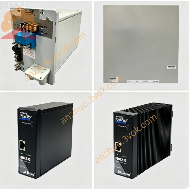
FOXBORO P0916PV I/A Series 16-Channel Low-Voltage Special Isolated Termination Assembly TA Module
Description
FOXBORO P0916PV Operation Specification Manual
1. Basic Module Information
2. Core Low-Voltage Signal Technical Parameters
Channel Configuration & Signal Compatibility
16 independent signal channels, grouped isolation per 8 channels
Low-voltage analog signals: 0–100mV, 0–500mV, 1–5VDC micro voltage signals
Discrete input: 12~30VDC low-voltage dry contact feedback signal
Discrete output: 24VDC low-power drive signal, single channel max load 0.2A low-inductance load
Precision Performance
Analog signal basic accuracy: ±0.015% Full Scale (ultra-high precision for low voltage)
A/D & D/A conversion resolution: 16-bit high precision
Input impedance of analog channel: ≥100MΩ to avoid tiny signal attenuation
Isolation & Low-Noise Protection Circuit
Dielectric isolation voltage between field side and control backplane ≥2500VAC
Ultra-low-noise filter circuit specially optimized for millivolt weak signals
Miniature TVS micro-surge absorption components to avoid small signal distortion
Independent micro-current short-circuit protection with automatic recovery
Dual-Color LED Diagnostic Indicators
Global operation indicator: Steady green = self-test passed normally; Flashing red = DB25 bus communication fault
Single channel LED: Green = normal weak signal loop; Red = open circuit, micro-short circuit or signal overload fault
3. Environmental Operating Specifications
4. Installation & Operating Instructions
Module Installation Steps
(1) Install standard 35mm DIN rail horizontally inside precision DCS control cabinet
(2) Snap P0916PV onto DIN rail and lock the bottom anti-slip buckle tightly
(3) Connect shielded DB25 communication cable between module backplane port and matched low-voltage FBM I/O module
Low-Voltage Micro-Cable Wiring Specifications
Weak signal cable: Ultra-fine twisted shielded pair wire, strictly separated from high-current power cables
All thin instrument wires are fixed by micro compression screws, avoid over-tightening to crush thin wire cores
Single-point shielding grounding inside cabinet to eliminate common-mode noise of low-voltage signals
24VDC power supply strictly distinguishes positive and negative poles, independent power supply loop for weak signal group
Power-On Startup & System Configuration Process
(1) Complete full wiring inspection and check all thin wire terminals for intact connection
(2) Close cabinet door and supply 24VDC power; module completes automatic self-diagnosis within 30 seconds
(3) Log into I/A Series operation workstation, configure low-voltage signal range and high-impedance filter parameters
(4) Download parameter configuration to FBM module, test millivolt weak sensor signal acquisition and low-power actuator driving effect
Routine Maintenance Rules
Check channel LED indicators and thin wire terminal tightness per shift
Clean tiny dust on precision terminals monthly to prevent micro-contact resistance drift
Inspect DB25 cable shielding integrity and wire insulation aging every half year
5. Safety Precautions
Live plugging/unplugging of DB25 communication cables and low-voltage micro signal wires is strictly prohibited. Cut off the 24VDC total power supply before wiring maintenance to avoid irreversible distortion of precision circuit components.
Keep the module far away from high-current frequency converters and large motors to prevent low-voltage weak signal noise interference.
Unauthorized disassembly of internal precision low-noise circuit boards is forbidden; internal circuit calibration and maintenance must be operated by Foxboro certified precision automation technicians.
If continuous red fault alarms appear on multiple channels, cut off power supply immediately to check thin wire breakage, micro-short circuit or sensor signal overload.
6. Fault Diagnosis & Troubleshooting Guide
All indicators off: Inspect cabinet 24VDC power supply circuit and loose power terminals
Single channel red fault light: Check low-voltage micro-sensor open circuit, thin wire breakage or terminal poor contact
Flashing global red light (bus communication failure): Verify DB25 cable shielding integrity and connector contact tightness
Low-voltage signal severe drift and noise fluctuation: Re-optimize independent wiring layout, reinforce single-point shielding grounding and increase low-noise filtering parameters
4. Application Fields (English Version)
Fine Chemical & Pharmaceutical Industry: Precision synthesis workshop, laboratory fermentation tank millivolt temperature/pH micro-signal collection
Petrochemical R&D Laboratory: Pilot reaction kettle low-voltage precision pressure and flow instrument signal wiring
New Energy Industry: Battery test workshop low-voltage voltage and current tiny signal centralized termination control
Water Quality Monitoring Industry: Laboratory water analyzer low-voltage sensor weak signal isolation transmission
Pulp & Paper R&D Lab: Paper material test bench micro-pressure low-voltage measuring signal processing
Food & Beverage Precision Processing: Aseptic workshop tiny temperature transmitter low-noise signal wiring
Environmental Monitoring Industry: Ambient gas trace detection low-voltage sensor signal collection
Precision Metallurgical Laboratory: Material test furnace thermocouple millivolt signal stable isolation transmission
Get a Quote