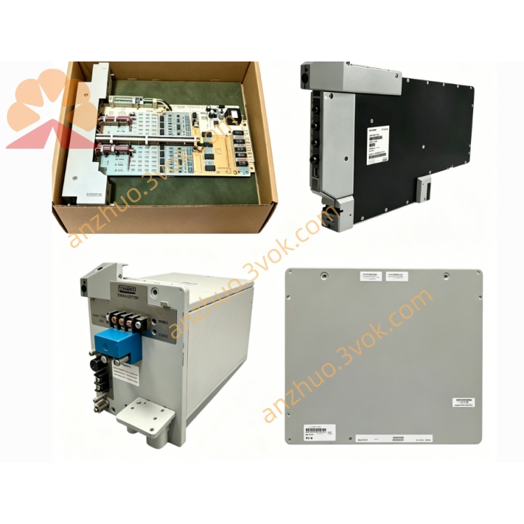
FOXBORO P0916PU I/A Series 16-Channel Waterproof & Dustproof Enhanced Termination Assembly TA Module
Description
FOXBORO P0916PU Operation Specification Manual
1. Basic Module Information
2. Core Mixed Signal Technical Parameters
Channel Configuration & Signal Compatibility
16 independent signal channels, grouped isolation per 8 channels
Analog signals: 4–20mA, 0–20mA DC current, 1–5VDC HART instrument signals
Discrete input: 15~60VDC dry contact feedback signal
Discrete output: 24VDC sink/source digital drive signal, max 0.5A inductive load per channel
Measurement & Output Performance
Analog basic accuracy: ±0.03% Full Scale
A/D & D/A conversion resolution: 16-bit high precision
Max allowable load resistance of analog channel: 500Ω
Isolation & Multi-Layer Protection Circuit
Dielectric isolation voltage between field side and control backplane ≥2500VAC
Analog channels: Current limiting resistors + dustproof bidirectional surge absorption filters
Discrete output channels: Built-in encapsulated freewheeling diodes to eliminate coil reverse EMF
Each channel independent short-circuit protection with automatic recovery, resistant to humid leakage current
Dual-Color LED Diagnostic Indicators
Global operation indicator: Steady green = self-test passed normally; Flashing red = DB25 bus communication fault
Single channel LED: Green = normal signal loop; Red = open circuit, short circuit or leakage fault
3. Environmental Operating Specifications
4. Installation & Operating Instructions
Module Installation Steps
(1) Install standard 35mm DIN rail horizontally inside semi-open control box or enhanced sealed cabinet
(2) Snap P0916PU onto DIN rail and lock the bottom anti-slip buckle tightly
(3) Thread field cables through silicone waterproof gaskets, then connect shielded DB25 cable between module backplane port and matched FBM I/O module
(4) Close the integrated dust cover of terminal block after wiring is completed
Dustproof & Waterproof Wiring Specifications
Field cables must pass through the matched silicone sealing gaskets to block dust and water vapor from entering the terminal area
Analog instrument cable: Shielded twisted pair wire, single-point shielding grounding inside cabinet
Digital control cable: Separate wiring duct layout, avoid parallel laying with high-voltage AC power cables
Retighten all compression screws every month to prevent contact resistance increase caused by dust deposition
24VDC power supply strictly distinguishes positive and negative poles; analog and digital groups use independent power loops
Power-On Startup & System Configuration Process
(1) Check sealing gaskets, dust cover and all terminal locking status completely
(2) Close cabinet door and supply 24VDC power; module completes self-diagnosis within 30 seconds
(3) Log into I/A Series workstation, configure channel signal types (AI/AO/DI/DO)
(4) Download parameter configuration to FBM module, test sensor acquisition and actuator driving under dusty humid environment
Routine Maintenance Rules
Check channel LED indicators, dust cover and sealing gaskets per shift
Open dust cover to clean terminal dust and oil stains monthly, then reinstall cover tightly
Inspect silicone gasket aging, DB25 cable oxidation and wire insulation damage every half year
5. Safety Precautions
Live plugging/unplugging of DB25 communication cables and field signal wires is strictly prohibited. Cut off the 24VDC total power supply before wiring maintenance to avoid burning internal isolation circuits.
Do not remove the terminal dust cover during normal operation to prevent dust and water vapor intrusion causing leakage and short circuit.
Unauthorized disassembly of internal circuit boards and damage to waterproof silicone structures are forbidden; internal circuit maintenance must be performed by Foxboro certified automation technicians.
If red fault alarms occur frequently in humid and dusty environments, cut off power supply immediately to check gasket aging, terminal damp leakage or cable insulation damage.
6. Fault Diagnosis & Troubleshooting Guide
All indicators off: Inspect cabinet 24VDC power circuit and loose power terminals caused by dust accumulation
Single channel red fault light: Check field wire damp leakage, wire breakage or terminal loose contact under dust coverage
Flashing global red light (bus communication failure): Verify DB25 cable shielding integrity and connector contact tightness
Analog signal severe fluctuation, digital signal random jump: Replace aging sealing gaskets, strengthen cabinet sealing and single-point shielding grounding
4. Application Fields (English Version)
Petrochemical Industry: Open-air auxiliary control boxes of refineries and ethylene plants, workshop high oil mist cabinet signal wiring
Oil & Gas Industry: Onshore oil field wellhead semi-sealed control box, natural gas transfer station dusty equipment signal termination
Thermal Power Industry: Coal-fired boiler coal conveying workshop, ash removal workshop high dust local control cabinet signal integration
Metallurgical Industry: Smelting furnace open control box, hot rolling mill water vapor & dust mixed environment signal processing
Water Treatment Industry: Sewage plant outdoor local control box, sludge workshop high humidity dust monitoring wiring
Pulp & Paper Industry: Paper making workshop humid steam environment, raw material conveying dust cabinet signal termination
Fine Chemical & Pharmaceutical Industry: Raw material feeding open workshop, solvent recovery semi-sealed control box signal collection
Cement & Building Materials Industry: Raw material silo bottom control cabinet, rotary kiln ash workshop heavy dust signal centralized wiring
Get a Quote