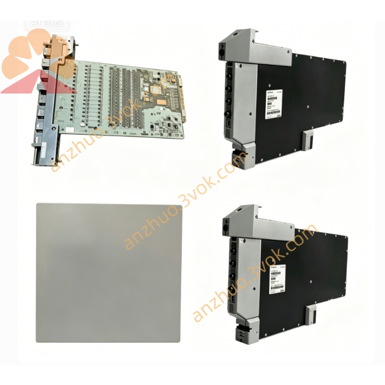
FOXBORO P0916PS I/A Series 16-Channel Intrinsically Safe Isolated Termination Assembly TA Module
Description
FOXBORO P0916PS Operation Specification Manual
1. Basic Module Information
2. Core Mixed Signal & Safety Technical Parameters
Channel Layout & Signal Compatibility
16 independent signal channels, 8 channels per isolated safety group
Analog signals: 4–20mA HART transmitter signal, 0–20mA, 1–5VDC
Discrete input: 15~60VDC dry contact limit switch feedback
Discrete output: 24VDC low-energy digital drive, single channel max safe load 0.3A
Intrinsic Safety Barrier Performance
Each channel built-in precision current-limiting, voltage-limiting safety barrier
Reinforced isolation withstand voltage between safe side and hazardous side ≥2500VAC
Maximum allowable input energy limited to avoid igniting flammable gas mixtures
Compatible with Ex ia IIC T6 field sensors and solenoid valves
Measurement & Transmission Precision
Analog signal basic accuracy: ±0.03% Full Scale
A/D & D/A conversion resolution: 16-bit high precision
Max analog channel load resistance: 500Ω
Multi-Layer Protection Design
TVS bidirectional surge absorption circuit for transient pulse suppression
Independent channel short-circuit protection with automatic recovery
Full-spectrum EMI/RFI filter to eliminate converter and motor interference
Dual-Color LED Diagnostic Indicator
Global running indicator: Steady green = self-test passed normally; Flashing red = DB25 bus communication fault
Single channel LED: Green = normal safe signal loop; Red = open circuit, short circuit or safety barrier overload fault
3. Environmental Operating Specifications
4. Installation & Operating Operation Guide
Module Installation Rules (Critical Safety Requirement)
(1) The P0916PS module must only be installed in non-hazardous safe-area DCS control cabinets
(2) Install standard 35mm DIN rail horizontally inside cabinet, snap module and lock bottom anti-slip buckle
(3) Connect shielded DB25 communication cable between module backplane port and matched FBM I/O module
Hazardous Area Wiring Safety Specifications
Field cables running to explosive zones must use intrinsically safe shielded twisted pair cables
Separate intrinsic safety wiring trough completely from high-voltage AC power and non-IS cables
All compression screw terminals must be fully tightened with specified torque to avoid poor contact spark risk
24VDC power supply strictly distinguishes positive and negative poles; single-point shield grounding in safe cabinet
Power-On Startup & System Configuration Process
(1) Complete full wiring inspection, verify IS cable separation and terminal tightness
(2) Close cabinet door and switch on 24VDC power supply; module completes automatic self-diagnosis within 30 seconds
(3) Log into I/A Series operation workstation, configure each channel signal type (AI/AO/DI/DO) and intrinsic safety parameters
(4) Download configuration to FBM module, test real-time hazardous area sensor acquisition and low-energy actuator driving performance
Daily Safety Maintenance Regulations
Check channel LED indicators and terminal tightness per production shift
Clear dust accumulated on terminals and safety barrier components monthly
Inspect DB25 cable aging, connector oxidation and wire insulation integrity every six months
Conduct annual safety barrier performance calibration by certified explosion-proof technicians
5. Safety Operation Precautions
Live plugging/unplugging of DB25 communication cables and intrinsically safe field wires is strictly prohibited. Cut off total 24VDC power supply before any wiring maintenance to eliminate spark risks.
This module is only for installation in safe control rooms; never mount P0916PS inside Zone 0/1/2 hazardous explosive areas.
Unauthorized disassembly of internal safety barrier circuit boards is forbidden; internal maintenance must be operated by Foxboro Ex-certified automation technicians.
If multiple channels continuously trigger red fault alarms, cut off power supply immediately to check field cable short circuit, wire breakage or overloaded safety barrier.
Do not replace non-certified field instruments on intrinsically safe loops, which will invalidate explosion-proof safety performance.
6. Fault Diagnosis & Troubleshooting Guide
All indicators off: Inspect cabinet 24VDC power supply circuit and loose power terminals
Single channel red fault light: Check hazardous area sensor/actuator open circuit, wire breakage or safety barrier overload
Flashing global red light (bus communication failure): Verify DB25 cable shielding integrity and connector contact tightness
Analog signal severe fluctuation, digital signal random jump: Reinforce independent IS cable routing and single-point shielding grounding
4. Application Fields (English Version)
Petrochemical Industry: Refinery, ethylene plant Zone 1 reactor, distillation column HART temperature/pressure transmitter intrinsically safe signal wiring
Oil & Gas Industry: Onshore crude oil extraction wellhead, natural gas compressor station, LNG storage tank hazardous area instrument signal isolation termination
Fine Chemical & Pharmaceutical Industry: Flammable solvent synthesis workshop, fermentation tank Zone 1 explosion-proof sensor and interlock switch signal processing
Thermal Power Industry: Chemical dosing area with combustible gas, hydrogen production station intrinsically safe monitoring signal centralized wiring
Water Treatment Industry: Biogas sewage treatment plant flammable gas detection sensors and emergency cut-off interlock safe signal transmission
Pulp & Paper Industry: Volatile solvent digestion workshop hazardous area pressure transmitters and safety limit switch IS wiring control
Metallurgical Industry: Coking plant flammable gas monitoring transmitters and furnace emergency interlock intrinsically safe signal collection
Chemical Raw Material Industry: Flammable liquid storage tank area liquid level, pressure, gas detection explosion-proof instrument unified termination assembly
Get a Quote