Emerson 3169926C0 Central Control Module
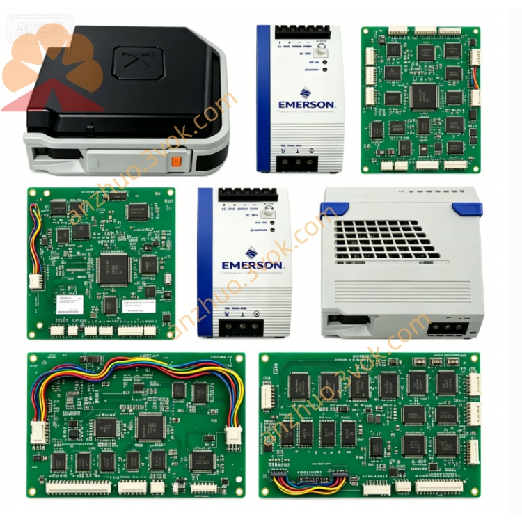
3169926C0 is a dedicated central control module (CCM) manufactured by Emerson for industrial DCS and centralized automation control system, serving as core master processing unit of the whole control rack system. This module is designed for continuous real-time process data collection, logic operation, field device communication and centralized operational management for petrochemical, power plant, water treatment and refining industrial sites. Equipped with built-in cooling fan for active heat dissipation inside enclosed metal housing, the module adopts integrated circuit encapsulation structure to enhance anti-interference performance under harsh factory electromagnetic environment.
Description
Built with industrial-grade enclosed metal housing and integrated built-in cooling fan structure, the product features stable heat dissipation performance to support long-duration continuous operation under harsh industrial ambient conditions. It is embedded with high-performance industrial processing chip and independent storage unit, supporting multiple core functional modules including real-time alarm & event management, historical production data trend logging, full-process batch production control and multi-type advanced closed-loop control algorithms. With outstanding hardware compatibility and system scalability, 3169926C0 can realize seamless communication docking and collaborative operation with third-party brand automation equipment, which effectively helps industrial sites optimize overall production efficiency, cut unnecessary energy consumption and stabilize finished product quality consistency. Main applicable scenarios cover petrochemical, thermal power, food processing, pharmaceutical manufacturing and other continuous production industries that require high-precision automatic control.
Part 2 English User Manual Content
Chapter 1 Safety Precaution
All installation, wiring, commissioning and maintenance operations on 3169926C0 must be completed by certified professional industrial electricians and automation maintenance technicians. Cut off all input power supply of the module and relevant peripheral equipment before any disassembly or wiring work to avoid electric shock or component burnout risk caused by live operation. Do not install the module in environment with severe corrosive gas, excessive dust accumulation, continuous water splash or ambient temperature exceeding the rated working range; prohibited to block the air inlet and outlet of the built-in cooling fan, as poor heat dissipation will lead to abnormal shutdown or permanent hardware damage of the module. Stop running immediately and cut off power once abnormal smoke, peculiar smell or irregular fan noise occurs during equipment operation, forbidden to power on repeatedly before troubleshooting.
Chapter 2 Installation Instruction
Select standard DIN rail or fixed cabinet installation mode according to on-site cabinet layout requirements, fix the module firmly inside closed industrial control cabinet to prevent loose displacement from mechanical vibration during equipment running. Complete all signal wiring and power wiring following the defined terminal definition sequence of product shell, separate strong-current power cable and weak-current signal cable layout to reduce electromagnetic interference impact on signal transmission accuracy. After wiring completion, check all terminal fastening tightness one by one to avoid virtual connection resulting in intermittent communication failure or module startup abnormality. Confirm cabinet ventilation condition meets heat dissipation demand before initial power supply access.
Chapter 3 Startup & Operation Guide
Complete pre-power inspection work as specified in installation chapter first, then access rated input power for the module and wait for self-check progress automatically. The module will finish hardware self-test and system initialization within specified startup duration; all indicator lamps on panel keep normal steady state after successful initialization, otherwise refer to fault troubleshooting chapter for abnormal indicator analysis. Log in matched upper computer configuration software after normal startup to complete communication parameter configuration, point address definition and control program download. After program verification passes, switch the module from manual debugging mode to automatic running mode to realize on-site equipment centralized control. Regularly check system running log, historical data record and real-time alarm information during daily operation, back up core configuration data periodically to prevent data loss from unexpected equipment failure.
Chapter 4 Daily Maintenance & Storage Requirements
Carry out regular maintenance inspection at fixed cycle, clean surface dust of module housing and cooling fan with dry soft brush, avoid using liquid cleaning agent to wipe circuit and terminal area directly. Check fan rotation status, terminal wiring tightness and indicator working condition in each maintenance; replace aging cooling component timely once abnormal fan speed or stuck rotation appears. When the module needs long-term standby storage, cut off all external power supply, detach all external connecting cables, place the product in dry, ventilated and room-temperature warehouse environment away from damp and corrosive substances, and conduct periodic power-on aging test for long-stored spare modules every half year.
Chapter 5 Fault Troubleshooting
If the module fails to start after power on, first verify input power voltage compliance with rated parameter and main power circuit connectivity, then check internal power fuse integrity of the equipment. When communication interruption happens between module and upper system, inspect communication wiring connection status, matching communication protocol parameter setting and surrounding strong electromagnetic interference source distribution. In case of frequent alarm information popping up during running, export historical alarm log to locate corresponding field equipment abnormal point or module internal control program configuration error; restore factory default setting and reload backup configuration file after confirming software configuration fault. Contact Emerson official after-sales technical support if internal hardware failure cannot be eliminated through above self-check steps.
Get a Quote