3A59104G01
Description
1. Basic Product Info
2. Electrical & Mechanical Parameters
Input Rating: AC auxiliary input + WESTBUS backplane pre-regulated DC input; multi-channel regulated DC output: +5VDC, ±12VDC for remote I/O signal acquisition boards and serial interface cards
Total Rated Output Power: 19.2W, independent overcurrent cutoff per each voltage rail
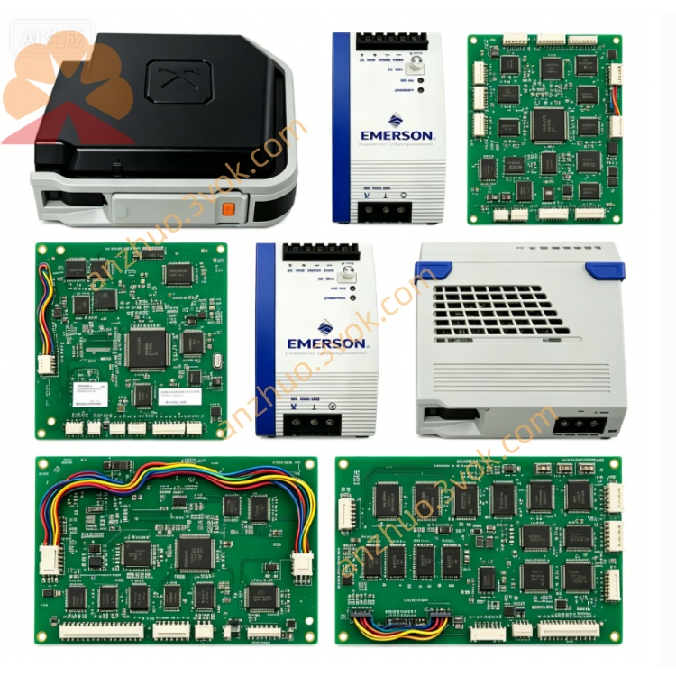
Dimension: Standard Eurocard plug-in form factor: 237mm × 164mm × 29mm, net weight:1.43kg
Environmental Specification: Continuous working ambient temperature: 0℃ ~ +55℃ inside sealed control cabinet; storage temperature: -40℃ ~ +85℃; full PCB conformal three-proof coating, anti-vibration component soldering; complies with UL safety certification and CE industrial EMC standards for thermal power and petrochemical automation equipment.
3. Core Functional Features
Centralized Multi-Rail Power Regulation: Supplies stable rated DC power to remote Q-line digital/analog I/O modules and onboard serial communication circuits within remote I/O subrack, converting unsteady backplane power to precision working voltage for field signal acquisition hardware.
Multi-layer Hardware Fault Protection: Equipped with independent overvoltage, overcurrent, short-circuit fuse and thermal shutdown protection for every output channel; automatically cuts faulty branch power to avoid cascaded burnout of adjacent plug-in I/O cards.
Front Panel Diagnostic Indication: Multi-color LED indicators for main AC input status, each DC output working condition and overheat/alarm signal; fault diagnostic data uploaded to DPU main controller via WESTBUS backplane for centralized system fault logging and alarm prompting.
Slot Isolated Maintenance Design: Supports single-slot power isolation and cold-swap card replacement without full remote rack power outage, effectively shortening field maintenance downtime for DCS control room overhaul.
4. Typical Application Range
5. Installation & Maintenance Guidelines
Cut off dedicated slot power supply before installation; align PCB guide rails with cabinet slots and insert vertically, fully lock front panel fixing buckles; verify all output voltage values within tolerance before rack power recovery.
Complete sequential installation of matched remote I/O input/output boards after power-on, execute full power supply and bus communication loop test to confirm normal system running.
Clean PCB surface dust and terminal contacts every six months; store spare modules inside ESD-controlled dry warehouse, perform quarterly short-time powered aging test to prevent electrolytic capacitor deterioration caused by long-term idle storage.
Get a Quote