3A5897618
Description
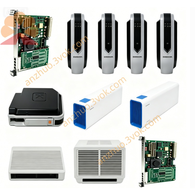
1. Product Introduction
2. Electrical & Mechanical Parameters
Power Supply: Powered by rack backplane +5VDC, ±12VDC; onboard isolated DC-DC regulator for auxiliary peripheral power output, rated power consumption: 14.7W
Bus Interface: Designed for WESTBUS backplane bus communication, realizes data exchange between MMI mainboard, CRT video card and keyboard/mouse interface card in one console rack; reserved auxiliary serial expansion port for peripheral expansion
Dimension: Standard Eurocard plug-in specification: 232×160×27mm, net weight:1.35kg
Ambient Spec: Continuous operating temperature: 0℃ ~ +55℃ inside sealed control cabinet; storage temperature: -40℃ ~ +85℃; full PCB three-proof conformal coating, anti-shock wave soldering; compliant with UL safety standard and CE industrial EMC certification for power plant automation equipment
3. Core Functional Features
Backplane Bus Signal Routing: Centralized signal transfer hub inside MMI rack, aggregates bus data of display driver card, keyboard & mouse communication card, forwards to main MMI controller via WESTBUS bus, optimizes internal wiring layout of operator station.
Multi-channel Auxiliary Power Distribution: Distribute stabilized auxiliary power to onboard peripheral interface slots, built-in over-current, over-voltage and short-circuit hardware fuse protection to avoid cascaded damage of adjacent plug-in boards caused by power abnormal fluctuation.
Built-in Hardware Fault Diagnosis: Multi-color LED status indicators on front panel for power input, bus communication status, each channel auxiliary power abnormal; fault codes can be uploaded to upper DPU monitoring system through backplane bus for centralized fault record and alarm prompting.
Cold Swap Maintenance Design: Allow single-slot power cut and independent card replacement without powering down the entire MMI rack, greatly shorten field maintenance downtime for control room overhaul.
4. Typical Application Scope
5. Installation & Maintenance Guidance
Cut off power supply of corresponding rack slot before installation, align card guide rail with cabinet slot and insert vertically, lock front panel fixing buckle firmly; verify backplane voltage specification matching before restoring cabinet power supply.
Match peripheral interface cards (video card, KB/Mouse card) into corresponding adjacent slots after power-on, test whole HMI input & display loop to confirm normal data interaction.
Conduct dust cleaning on PCB surface and terminal positions every six months; store spare modules in dry, non-corrosive, ESD-protected warehouse, perform quarterly short-time power-on inspection to prevent component performance degradation caused by long-term shelf storage.
Get a Quote