3A59323G01
Description
1. Product Introduction
2. Electrical Specifications
Input Power: Dual feeding design from cabinet auxiliary AC source + WESTBUS backplane pre-regulated DC power supply
DC Output: Multi-channel regulated output of +5VDC, +12VDC, -12VDC; total rated continuous output power: 25W; every single output rail equipped with independent overvoltage, overcurrent, short-circuit and thermal cut-off protection circuit
Indicator Layout: Front-panel LED indicators for input power status, individual channel output status and overheat fault alarm
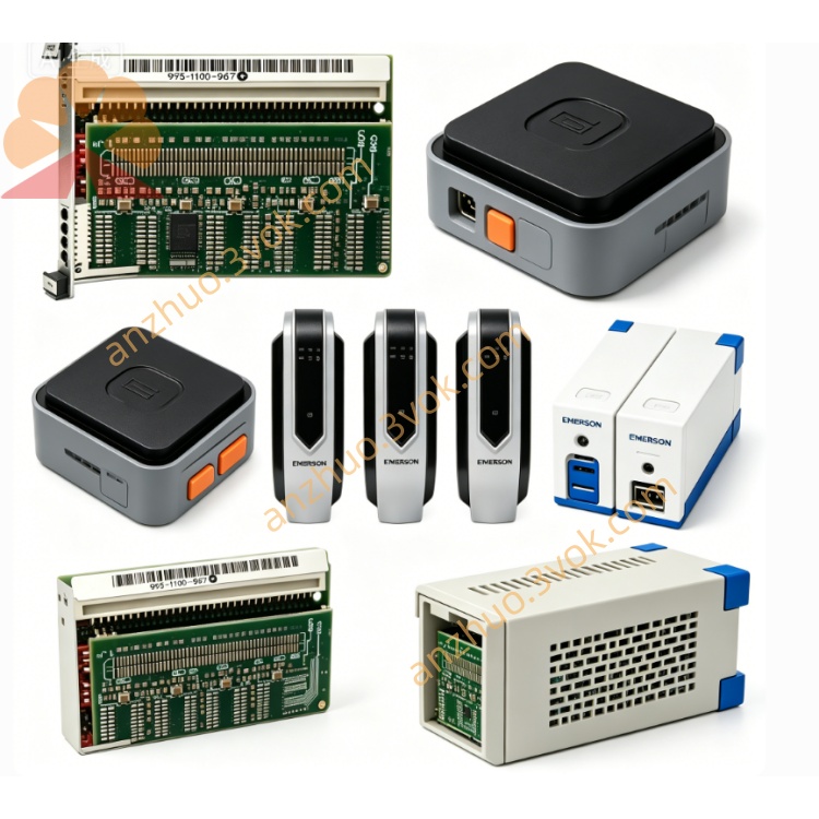
Mechanical Dimension: Standard Eurocard plug-in size matching Q-Line rack slot specification
Ambient Parameter: Continuous operating temperature: 0℃ ~ +55℃ inside sealed control cabinet; storage temperature: -40℃ ~ +85℃; certified with UL safety standard and CE industrial EMC compliance for power generation automation equipment
3. Core Functional Features
Centralized Rack Power Feeding: Supplies stable operating voltage to all Q-Line analog/digital I/O cards (AI/DI/AO/DO) and onboard WESTBUS communication transceiver circuits installed within the same subrack.
Independent Fault Isolation: Single faulty output channel triggers automatic power cutoff only for the failed circuit, preventing cascaded damage to adjacent plug-in modules on the rack.
WESTBUS Diagnostic Upload: All fault codes and abnormal status data are transmitted via WESTBUS field bus to DPU main controller for centralized system logging and remote HMI alarm popup on operator workstation.
Slot-level Cold Swap Support: Defective module can be replaced by cutting only corresponding slot power instead of full cabinet power outage, drastically shortening on-site maintenance downtime.
4. Difference Between G01 and G02 Revision
3A59323G01 (Original First Generation): Basic standard circuit configuration with conventional grade electrolytic capacitors and regular PCB layout design, standard EMI filtering performance for general cabinet environment.
3A59323G02 (Optimized Upgraded Version): Improved input anti-interference filter circuit, full adoption of high-temperature resistant industrial capacitors and optimized component derating design; enhanced three-proof conformal coating on PCB to improve dustproof, damp-proof and anti-corrosion capability for harsh petrochemical/thermal power plant working conditions.
5. Typical Application Scope
6. Installation & Maintenance Guidelines
Cut off dedicated slot power completely before disassembly and installation; wear qualified ESD anti-static wrist strap to avoid static damage to onboard electronic components.
Insert module vertically along cabinet guide rail and lock front panel fixing buckle tightly; verify all output voltage within rated tolerance range after power restoration.
Install corresponding AI, DI, AO, DO I/O modules sequentially and complete full power loop & WESTBUS communication commissioning test after power-on.
Carry out regular dust cleaning on PCB surface and terminal contacts every six months for in-service modules; store spare cards in dry ESD-controlled warehouse and implement quarterly short-duration powered burn-in test to prevent capacitance degradation from long-term idle storage.
Get a Quote