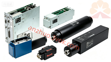
DKC06.3-040-7-FW | Rexroth Indramat ECODRIVE06 DeviceNet Bus 40A High-Voltage Power Base
Description
Model Explanation
DKC: ECODRIVE series all-digital servo power amplifier
06: Hardware native DeviceNet bus communication architecture
.3: Third-generation ECODRIVE03 power hardware platform
040: Rated continuous output current 40A
7: 700VDC bus high-voltage model, three-phase AC380~480V input
FW: Power base without main control card, without control firmware, requires MGP-7 main control card for compatibility use Technical Specifications
Main power supply: Three-phase AC 200~480V ± 10%, 50/60Hz, maximum input current for the entire machine is 16A; independent DC 24V control power supply, control power consumption is 27W. Indramat USA
DC bus: Nominal 700VDC, overvoltage protection 850VDC, built-in pre-charge circuit, bus capacitor 0.41mF
Output specifications: Continuous rated 40A, overload for 240% can last for 400ms, carrier 4kHz/8kHz selectable, maximum output frequency 1000Hz
Braking configuration: Built-in short-term peak braking 17.5kW (0.5s), continuous braking 7.2kW・s, heavy-load conditions require external braking resistor
Dimensions: Width 65mm × Height 360mm × Depth 261mm, net weight 5.7kg, IP20 cabinet installation protection Indramat USA
Environmental conditions: Full-load operation at 0~40℃, altitude ≤1000m; storage at -30~+85℃, humidity < 95% without condensation
Interface and communication configuration
Power terminals: L1/L2/L3 three-phase input, U/V/W motor power terminals, dedicated connection position for external braking resistors
Encoder interface: Compatible with rotary transformers, TTL incremental ABZ, Sin/Cos full series of encoder feedback
Slot configuration: Built-in dedicated slot for MGP-7 main control board, control board leads DI/DO switch quantity, ±10V analog instructions, pulse direction point interface
Communication ports
1. RS232 debugging serial port (enable MGP board): IndraWorks parameter debugging, firmware burning and upgrading
2. X60 terminal native DeviceNet bus interface (06 series fixed DeviceNet protocol), optional DKC06.3-LK-DVN01 communication expansion card to optimize bus stability
3. Optional additional sub-card to expand RS485 communication Core function
The main body only includes inverter power hardware. The entire position/velocity/torque three-loop closed-loop control is achieved through the MGP-7 main control card and the accompanying firmware;
Supports ±10V analog speed control, pulse position control, DeviceNet bus multi-axis electronic gear synchronization, origin return to zero, and linkage with motor brake timing;
Integrated full hardware fault protection: IGBT short circuit, output overcurrent, bus over/under voltage, power module over-temperature, encoder break wire self-lock shutdown. Applicable scenarios
Numerical control machining center feed axis, high-speed carton packaging main drive, wide-format rotary printing machine auxiliary shaft, automated transplanting mechanical hand, lithium battery cutting equipment driven servo.
Usage and Maintenance
1. Models with suffix 1.7 that use high-voltage power supply must not be connected to a three-phase AC220V power grid. Only AC380~480V power supply is allowed. Incorrect connection will directly damage the power module;
2. The FW bare base cannot be powered on independently. It must be matched with the same power MGP-7 main control card + corresponding power firmware to be debugged and operated;
3. For high-frequency start-stop loads with large inertia, an external large-power braking resistor must be installed to avoid overheating and damage of the built-in braking circuit;
4. DKC06 (DeviceNet), DKC05 (CANopen), and DKC04 (PROFIBUS) have similar installation dimensions, but the bus hardware is incompatible. It is not possible to directly replace spare parts across series.
Get a Quote