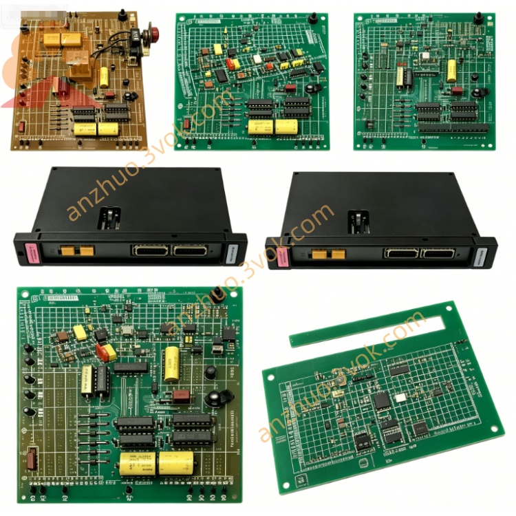
RELIANCE 61C-542 rack-mounted bipolar voltage analog input module
61C-542 is a rack-mounted bipolar voltage analog input module belonging to Reliance AutoMax/AutoMate 61C series distributed I/O product family, specially designed for collecting ±10VDC standard voltage signals from industrial displacement sensors, potentiometers and voltage-type transmitters on production field. The original production has been discontinued by manufacturer, available market products mainly include surplus unused original stock and fully calibrated refurbished modules, serving spare replacement and maintenance renovation of legacy metallurgy, papermaking, chemical and old-generation mechanical automation control systems.
Description
Product Introduction
61C-542 is a rack-mounted bipolar voltage analog input module belonging to Reliance AutoMax/AutoMate 61C series distributed I/O product family, specially designed for collecting ±10VDC standard voltage signals from industrial displacement sensors, potentiometers and voltage-type transmitters on production field. The original production has been discontinued by manufacturer, available market products mainly include surplus unused original stock and fully calibrated refurbished modules, serving spare replacement and maintenance renovation of legacy metallurgy, papermaking, chemical and old-generation mechanical automation control systems.
Model Definition
61C stands for unified series code of Reliance rack I/O product lineup. Numerical code 542 represents fixed specification of 16-channel ±10VDC voltage analog input type without built-in loop power supply. Base version 61C-542 has no hardware revision suffix, while upgraded variant 61C-542 optimizes internal filter circuit and component layout, keeping full mechanical compatibility and pin-to-pin interchangeability with other modules inside 61C series rack.
Technical Specifications
Nominal input signal range covers bipolar -10VDC to +10VDC, supporting flexible wiring configuration between 16 single-ended input channels or 8 differential input channels via upper system programming. Equipped with first-order low-pass filtering circuit with 7Hz cutoff frequency to restrain high-frequency field interference signal. Internal A/D conversion resolution reaches 12-bit, bipolar conversion count range from -4095 to +4095, unipolar mode from 0 to 4095, full-scale measurement accuracy controlled within ±0.2%FS under rated working condition. Module draws operating power entirely from backplane bus without external auxiliary power source. Continuous operating ambient temperature ranges from -20℃ to +55℃, storage temperature spans -40℃ to +85℃, applicable working humidity is 5%~95% non-condensing environment, passes UL and CE industrial safety certification and follows unified DIN rack installation dimension of 61C series.
Interface and Communication Configuration
Rear side is fitted with proprietary dedicated backplane bus connector to plug into AutoMax system rack backplane, exchanging real-time sampled analog digital data with host CPU through manufacturer exclusive internal bus protocol. Front panel is configured with detachable screw-type terminal block for field voltage signal wiring, matching external terminal adapter board for long-distance field wiring expansion. One global module running status LED is mounted on front panel to indicate module power supply and communication operating state, no independent channel separate indicator lamps arranged. No onboard RS485 or Modbus external communication port, all data interaction relies exclusively on rack backplane bus transmission.
Core Functions
Receive ±10VDC continuous analog voltage signal from on-site voltage-type sensors and converters, filter abnormal spike interference via built-in low-pass circuit, convert analog voltage into standard digital quantity through high-precision A/D conversion chip, then cyclically upload converted digital data to upper AutoMax PLC controller via backplane bus. Channel wiring mode switching between single-ended and differential is realized through upper control software parameter setup to adapt different field anti-interference demands. Supports mixed installation with other digital I/O and analog output modules of 61C series on same control rack for flexible distributed analog signal collection layout.
Application Scenarios
Mainly applied for stroke detection of hydraulic and pneumatic cylinders, displacement monitoring of rolling mill equipment, potentiometer signal collection of papermaking mechanical transmission parts, voltage signal pickup of industrial weighing and speed measuring sensors, as well as spare part replacement for renovation projects of outdated chemical and textile production line control cabinets with scattered voltage measuring points.
Operation and Maintenance Instructions
Cut off total rack power supply and wait more than 15 minutes for internal capacitor residual electricity release before module disassembly, replacement or field terminal rewiring. Conduct semi-annual routine maintenance including tightening terminal fastening screws, clearing internal accumulated dust with dry low-pressure compressed air and checking terminal pin oxidation condition. When abnormal measured data or module indicator off occurs, firstly inspect external sensor wiring and input voltage range, replace whole 61C-542 module only after eliminating all peripheral circuit faults. Avoid long-term over-range input voltage exceeding ±12VDC to prevent burnout of internal A/D conversion circuit components.
Get a Quote