RELIANCE 610113T original control signal processing circuit board
610113T is an original control signal processing circuit board manufactured by Reliance Electric, customized for legacy DC variable speed drive control system, acting as intermediate signal acquisition and feedback conversion component inside FlexPak series drive cabinet. It collects real-time current, voltage and speed feedback signals from drive power loop, converts analog field signals into standard low-level digital signals for main control board calculation and closed-loop regulation. The original manufacturer has terminated formal production; available products on market consist of surplus new stock and factory-tested refurbished units for on-site maintenance and spare part replacement of old industrial drive equipment.
Description
Product Introduction
610113T is an original control signal processing circuit board manufactured by Reliance Electric, customized for legacy DC variable speed drive control system, acting as intermediate signal acquisition and feedback conversion component inside FlexPak series drive cabinet. It collects real-time current, voltage and speed feedback signals from drive power loop, converts analog field signals into standard low-level digital signals for main control board calculation and closed-loop regulation. The original manufacturer has terminated formal production; available products on market consist of surplus new stock and factory-tested refurbished units for on-site maintenance and spare part replacement of old industrial drive equipment.
Model Definition
Numerical code 610113 represents fixed hardware platform code of Reliance standard feedback signal board for FlexPak drive series, defining unified PCB layout, basic circuit framework and original component specification of this product family. Letter suffix T stands for temperature-enhanced revised version, with upgraded high-temperature resistant original components and optimized anti-interference filtering circuit compared with standard base model, fully mechanically and electrically interchangeable with non-T suffix counterpart without cabinet modification.
Technical Specifications
Rated working input power is 24VDC ±10% supplied from internal drive auxiliary power source. Analog signal input range covers 0–10VDC for speed feedback and 0–5VDC for current sampling signal. Continuous working ambient temperature ranges from -20℃ to +75℃, short-time permissible peak operating temperature spans -35℃ to +85℃. Storage environment temperature is -40℃ to +90℃ under dry non-corrosive atmosphere. Working relative humidity keeps 5%–90% without condensation. Dielectric withstand voltage between PCB wiring and base substrate reaches 800VAC for one minute insulation test. Overall circuit follows industrial through-hole component assembling standard of Reliance original factory.
Interface and Communication Configuration
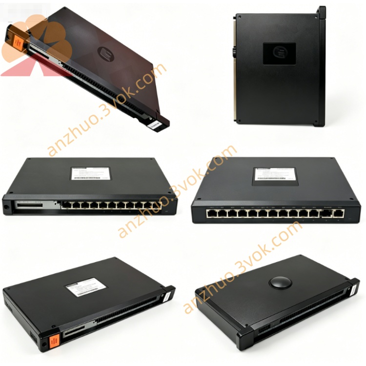
All signal transmission adopts hard-wired terminal wiring layout, split into three independent terminal groups including auxiliary power input terminal, field feedback signal input terminal and processed control signal output terminal. Input terminals connect to drive shunt and speed detection sensor via fixed wiring, output terminals transmit conditioned feedback signals to main control motherboard. No built-in fieldbus, RS485 or other digital communication chips, all data delivery depends on analog hard wiring without backplane plug-in bus docking design. Multiple onboard LED indicator points display power status and signal channel working state respectively.
Core Functions
Accurately sample real-time operating current and armature voltage signals from DC drive power circuit, filter out high-frequency interference spike from industrial power grid via internal RC filtering circuit, normalize raw sampled signals into stable standard analog signals matching main controller input requirement. Cooperate with main control unit to realize closed-loop speed and current dual-loop adjustment of DC motor, automatically feed back load fluctuation data to adjust thyristor trigger angle for constant torque output. Embedded overvoltage and overcurrent protection circuit cuts off abnormal signal output instantly when sampling circuit suffers surge impact to protect upper main control board from damage.
Application Scenarios
Mainly matching Reliance FlexPak series medium and large capacity DC speed regulating drives and supporting DC driving motors. Widely used in metallurgical rolling production line main transmission cabinet, papermaking equipment roller drive control cabinet, chemical industry large fan and water pump DC speed control system, as well as spare replacement for outdated textile, mining and printing machinery original Reliance drive control units.
Operation and Maintenance Instructions
Cut off complete AC main power of matched drive cabinet and wait no less than 20 minutes to release residual capacitance charge inside equipment before disassembling or installing the board. Fasten all wiring terminals firmly to avoid poor contact leading to signal distortion and drive abnormal speed fluctuation or overload alarm. Prevent strong mechanical shock and severe vibration during installation to avoid component solder joint desoldering. Perform annual routine maintenance to clear PCB surface accumulated dust with low-pressure dry compressed air, check terminal wire insulation aging condition regularly. Forbid random disassembly of encapsulated internal components; execute whole-board replacement once internal circuit breaks down after eliminating external wiring and power supply faults.
Get a Quote