RELIANCE 608870-73R original gate coupling control circuit board
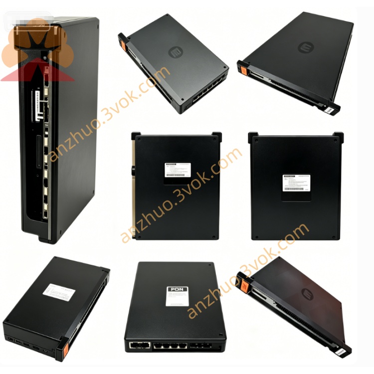
608870-73R is an original gate coupling control circuit board developed and manufactured by Reliance Electric, specially designed for FlexPak Plus series DC variable speed drives. It serves as the intermediate signal conversion module between drive main control board and power thyristor unit, converting low-level control pulse signals from mainboard into drive gate trigger signals for power semiconductor components. This component belongs to discontinued legacy industrial spare parts, no formal mass production from original factory currently; available commodities on market mainly consist of brand-new surplus inventory and factory-calibrated refurbished products for old drive system maintenance and replacement in heavy-duty industrial production lines.
Description
Product Introduction
608870-73R is an original gate coupling control circuit board developed and manufactured by Reliance Electric, specially designed for FlexPak Plus series DC variable speed drives. It serves as the intermediate signal conversion module between drive main control board and power thyristor unit, converting low-level control pulse signals from mainboard into drive gate trigger signals for power semiconductor components. This component belongs to discontinued legacy industrial spare parts, no formal mass production from original factory currently; available commodities on market mainly consist of brand-new surplus inventory and factory-calibrated refurbished products for old drive system maintenance and replacement in heavy-duty industrial production lines.
Model Definition
The prefix 608870 stands for unified part number of Reliance standard gate coupling board product platform for FlexPak Plus drive series. Middle two digits 73 define fixed internal circuit layout, original component configuration and preset trigger parameter specification of this sub-model. Suffix R denotes revised hardware version with optimized surge suppression circuit and upgraded terminal anti-interference design compared with base version of same serial code, while compatible with full range of matching drive models without mechanical modification.
Technical Specifications
Rated input control signal voltage ranges 3.8VDC to 5.2VDC from drive main controller. Output gate trigger rated voltage is 12VDC with peak transient output current reaching 450mA for thyristor driving. Normal continuous working ambient temperature spans -15℃ to +70℃, short-time allowable operating temperature covers -30℃ to +80℃. Storage temperature ranges from -40℃ to +85℃ under dry environment without corrosive vapor. Insulation withstand voltage between circuit trace and board substrate is 1000VAC for one-minute dielectric strength test. Standard working relative humidity is 5% to 90% non-condensing. The whole circuit board adopts through-hole electronic component layout conforming to Reliance original industrial grade component standard.
Interface and Communication Configuration
This board is equipped with fixed multi-core pre-wired harness terminals for hard-wired connection, divided into two signal areas including input control terminal group and thyristor gate output terminal group. Input terminals receive analog and pulse control signals from upper main control board via fixed wiring, output terminals directly connect to each thyristor gate and cathode terminal of drive power unit. No integrated fieldbus chip, RS485 or other digital communication interfaces, all signal transmission depends on hardwired analog and pulse wiring mode, no pluggable bus backplane docking structure.
Core Functions
It receives speed regulation and phase control low-level pulse signals transmitted from drive master control circuit, then amplifies and shapes original weak control signals into stable gate driving pulses that meet thyristor turn-on requirement. Realizes synchronous phase triggering of multiple power thyristors inside DC drive to finish AC to DC rectification conversion and motor speed closed-loop adjustment. Built-in internal transient voltage absorption and overcurrent protection circuit suppress instantaneous surge voltage from power loop, preventing damage of front-end main control board and back-end power components from abnormal voltage spike during drive startup and load mutation.
Application Scenarios
Exclusively matched with Reliance FlexPak Plus series large and medium capacity DC speed regulating drives and supporting DC drive motors. Widely applied in main transmission control system of metallurgical rolling mill equipment, papermaking machine main roller drive unit, chemical plant large pump and fan DC speed control cabinet, as well as spare part replacement for outdated printing, textile and mining conveyor DC drive equipment with original Reliance control configuration.
Operation and Maintenance Instructions
Completely cut off main AC input power of matched drive cabinet and wait at least 15 minutes for internal capacitor residual charge release before disassembly and installation operation. Keep all wiring terminals in tight fastening state to avoid poor contact causing unstable trigger signal and abnormal drive overcurrent fault. Prevent severe vibration and heavy impact on circuit board surface during installation to avoid loose soldering of internal original components. Conduct annual regular maintenance to check wire insulation aging and dust accumulation on PCB surface, remove surface dirt with dry compressed air at low air pressure. Random disassembly of onboard encapsulated original components is prohibited; whole board replacement is required once internal circuit fails after excluding external wiring and power supply faults.
Get a Quote