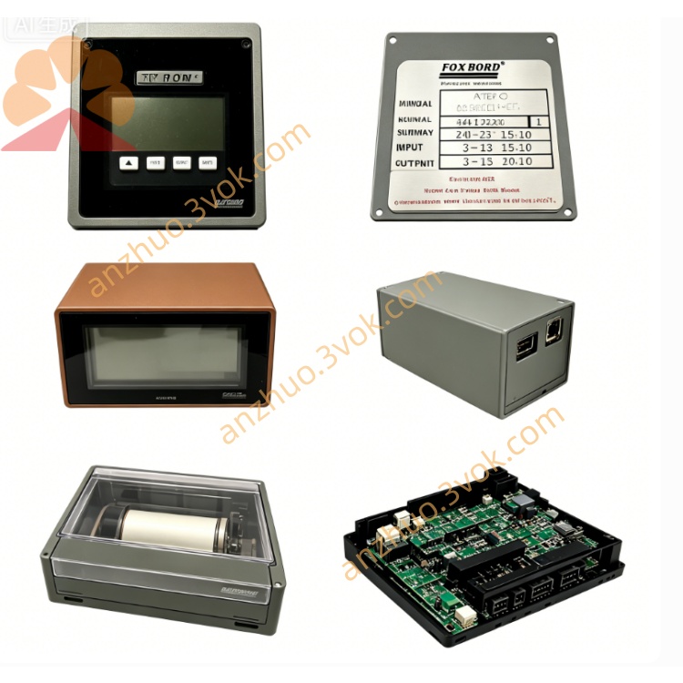
Foxboro FBM41A / FBM42A Digital I/O Module
Description
Foxboro FBM41A / FBM42A (P0902XA‑0C / P0902YA‑0C)
60 VDC 8‑Channel Isolated Discrete Input/Output Module
Specifications & User Guide (Copy‑Ready English)
General
Models: FBM41A (P0902XA‑0C) / FBM42A (P0902YA‑0C)
System: Foxboro I/A Series / EcoStruxure Foxboro DCS
Type: 8‑channel galvanically isolated discrete (60 VDC) I/O modules
Difference:
FBM41A: 8DI / 8DO (standard density)
FBM42A: 8DI / 8DO (high‑power output)
Redundancy: 1:1 hot‑swap redundant capable
Hot Swap: Supported (no system shutdown)
Certification: CE, UL, CSA, ATEX; Class I Div 2 / Zone 2
Environment: Class G3 (harsh industrial)
Operating Temp: 0 °C to +60 °C
Storage Temp: −40 °C to +85 °C
Humidity: 5–95 % non‑condensing
Enclosure: Die‑cast aluminum, IP20 rated
Dimensions: 140 mm × 165 mm × 45 mm
Weight: 0.68 kg (FBM41A); 0.72 kg (FBM42A)
I/O Channel Specifications (Common)
Configuration: 8DI + 8DO (channel‑to‑channel & channel‑to‑ground isolated)
Isolation: 600 VAC (1 min)
Status LEDs: 8 channel (ON/FAULT) + module RUN/FAULT
Termination: P0500RY / RH914TG TA (order separately)
Discrete Inputs (8 channels, both models)
Signal Type: Voltage monitor (15–60 VDC)
On‑State: 15–60 VDC; Off‑State: 0–5 VDC
Input Current: 2–6 mA @ 24 VDC
Debounce: Configurable (4 / 8 / 16 / 32 ms)
Open‑Circuit Voltage: 24 VDC ±20 %
Short‑Circuit Current: ≤5 mA
Discrete Outputs (8 channels)
FBM41A (Standard)
Type: Solid‑state switch (external ≤60 VDC)
Rating: 0.25 A / channel; 2 A total max
On‑Resistance: ≤1 kΩ
Off‑Leakage: ≤0.25 mA
Overload Protection: Per channel, auto‑recovery
FBM42A (High‑Power)
Type: High‑current solid‑state switch (external ≤60 VDC)
Rating: 2.25 A / channel; 12 A total max
On‑Resistance: ≤0.4 Ω @ 1 A
Off‑Leakage: ≤0.5 mA
Short‑Circuit Handling: Unlimited duration; 1‑s shutdown on overload
Power
Supply: 24 VDC (±5 % / −10 %), redundant
Consumption:
FBM41A: 9 W (single); 14 W (redundant)
FBM42A: 12 W (single); 18 W (redundant)
Heat Dissipation:
FBM41A: 8.5 W (single); 13 W (redundant)
FBM42A: 11.3 W (single); 17 W (redundant)
Communication
Fieldbus: Redundant 2 Mbps backplane (I/A Series)
Protocol: Foxboro proprietary
Data Update: 50 ms (default)
Basic Installation & Usage
Mounting
Snap into standard I/A Series DIN rail or baseplate.
Secure latch; ensure full seating for backplane contact.
Wiring
DI: Connect 15–60 VDC sensors/switches; no common ground needed (isolated).
DO: Connect external 12–60 VDC source; positive to load, negative to module.
FBM42A: Use 16–12 AWG for high‑current loads.
Shielded twisted pair recommended; separate analog/digital cables.
Configuration (I/A Series Software)
Set DI debounce time and alarm thresholds.
Configure DO failsafe (hold / ON / OFF).
Enable diagnostics (open load, short circuit, overcurrent).
Assign redundancy role (primary/secondary) if applicable.
Operation
RUN (green): module ok; FAULT (red): error (comms/power/channel).
Channel LED: ON = active; FLASH = fault.
Monitor DI status and DO commands in HMI.
Maintenance
Hot‑swap faulty module (no shutdown; TA wiring intact).
Inspect TA wiring, shields, and grounds annually.
Update firmware via I/A Series software.
Calibration: Not required (factory‑calibrated; on‑board diagnostics).
Typical Applications
FBM41A: Standard 24–60 VDC on/off control (solenoids, motor starters, contactors); status monitoring (limit/pressure switches).
FBM42A: High‑power 60 VDC loads (large solenoids, DC motors, heaters); heavy‑duty process skids.
Key Differences Summary
FBM41A: 0.25 A/channel, 2 A total; general‑purpose.
FBM42A: 2.25 A/channel, 12 A total; high‑power, heavy loads.
Get a Quote