Foxboro FBM37 RTD Temperature Input Module
Description
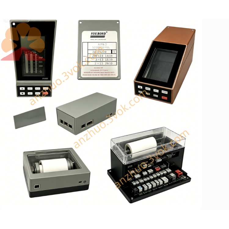
Foxboro FBM37 (P0400HH) – 8‑Channel Isolated Analog Output Module
Specifications & User Guide (Copy‑Ready English)
General
Model: FBM37 (P0400HH)
System: Foxboro I/A Series / EcoStruxure Foxboro DCS
Type: 8‑channel galvanically isolated analog output (AO) module
Function: 0–20 mA / 4–20 mA control signals for valves, actuators, VFDs
Redundancy: 1:1 hot‑swap redundant capable
Hot Swap: Supported (no system shutdown)
Certification: CE, UL, CSA, ATEX; Class I Div 2 / Zone 2
Environment: Class G3 (harsh industrial)
Operating Temp: 0 °C to +60 °C
Storage Temp: −40 °C to +85 °C
Humidity: 5–95 % non‑condensing
Enclosure: Die‑cast aluminum, IP20 rated
Dimensions: 140 mm × 165 mm × 45 mm
Weight: 0.65 kg
I/O Channel Specifications
Channels: 8 galvanically isolated (channel‑to‑channel & channel‑to‑ground)
Signal Range: 0–20 mA (default); 4–20 mA (configurable)
Resolution: 13‑bit
Accuracy: ±0.05 % of span (includes linearity)
Temperature Coefficient: ±50 ppm/°C
Output Delay: ≤30 ms (max)
Isolation: 600 VAC (1 min) channel‑to‑channel & channel‑to‑ground
Short‑circuit & Overload Protection: Per channel (current‑limited, auto‑recovery)
Load Resistance: 0–750 Ω (20 mA @ 18 VDC compliance)
Status LEDs: 8 channel (ON/FAULT) + module RUN/FAULT
Power
Supply: 24 VDC (±5 % / −10 %), redundant
Consumption: 10 W (single); 16 W (redundant pair)
Heat Dissipation: 9.5 W (single); 15.3 W (redundant pair)
Communication
Fieldbus: Redundant 2 Mbps backplane (I/A Series)
Protocol: Foxboro proprietary
Data Update: 50 ms (default)
Basic Installation & Usage
Mounting
Snap into standard I/A Series DIN rail or baseplate.
Secure latch; ensure full seating for backplane contact.
Wiring
Connect field devices (control valves, positioners, VFDs) to TA (Termination Assembly).
2‑wire AO: (+) from module, (−) to device; common ground not required (isolated).
Use shielded twisted pair; separate analog and digital cables.
Wiring size: 0.2–4 mm² (24–12 AWG); ferrules recommended for stranded wire.
Configuration (I/A Series Software)
Set signal range: 0–20 mA or 4–20 mA.
Configure scaling, failsafe state (hold / 0 % / 100 %), and update rate.
Enable channel diagnostics (short circuit, open load, overrange).
Assign redundancy role (primary/secondary) if applicable.
Operation
RUN (green): module ok; FAULT (red): error (comms, power, channel fault).
Channel LED: ON = active; FLASH = fault (short/open/overload).
Monitor output values, status, and diagnostics in HMI.
Maintenance
Hot‑swap faulty module (no shutdown; TA wiring remains intact).
Inspect TA wiring, shields, and grounds annually.
Update firmware via I/A Series software.
Calibration: Not required (factory‑calibrated; on‑board diagnostics).
Typical Applications
Analog control outputs for control valves and actuators.
4–20 mA signals for variable frequency drives (VFDs) and motor controllers.
Interface to non‑HART analog devices in process industries.
Migration of legacy 100‑series FBMs (e.g., FBM05) to modern I/A Series systems.
Get a Quote