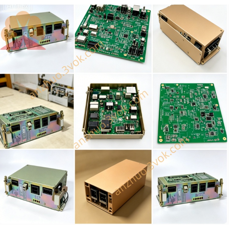
SGDL-01BP
SGDL-01BP belongs to Yaskawa Sigma mini economical AC servo drive series with rated power 100W. It is designed exclusively for pulse position control with single-phase AC100V input, matched with SGML-01 series 100W servo motor. Compact DIN rail mounting and small dimension make it ideal for compact precision automation equipment.
Description
1. Product Overview
SGDL-01BP belongs to Yaskawa Sigma mini economical AC servo drive series with rated power 100W. It is designed exclusively for pulse position control with single-phase AC100V input, matched with SGML-01 series 100W servo motor. Compact DIN rail mounting and small dimension make it ideal for compact precision automation equipment.
Model code explanation: SGDL denotes compact economical servo drive family; 01 stands for 100W rated power; B means single-phase AC100V power input; BP represents factory preset dedicated position-only control specification without analog speed or torque control function.
2. Electrical Specifications
Main power supply is single-phase AC100~115V, 50/60Hz. Rated continuous output current is 2.2A and peak transient output current reaches 7.1A for maximum 3 seconds to cope with startup impact load. Control circuit takes power directly from main input without separate external DC24V auxiliary supply for simpler wiring. The unit adopts natural convection cooling without built-in cooling fan, IP20 protection grade and approximate net weight 0.9kg for DIN rail snap-on installation.
It uses internal IGBT PWM drive and closed-loop position feedback via dedicated incremental serial encoder, and absolute encoder is not supported for this model.
3. Control Functions and Interfaces
Two standard connectors are equipped on the drive. CN1 is control terminal for external pulse command from PLC or motion controller, accepting both differential driver and open-collector pulse signals with maximum input frequency 250kpps and programmable electronic gear ratio for flexible mechanical ratio adjustment. CN2 is dedicated encoder port connected to motor feedback cable for closed-loop position detection.
Hardware is fixed for position control only; speed mode or torque mode cannot be switched by parameter setting. Motion distance is determined by total input pulse count and rotating speed by pulse frequency. No RS485 communication port is available; all parameter configuration is completed via onboard DIP switches and trimmer potentiometers without dedicated PC tuning software. Multiple built-in protection functions include overcurrent, undervoltage, overspeed, encoder break and overload protection, and alarm status is latched until power cycle reset.
4. Installation and Environmental Requirements
Operating ambient temperature ranges from 0°C to +55°C, storage temperature from -20°C to +85°C. Relative working humidity shall not exceed 90%RH without condensation; avoid corrosive gas, heavy dust and liquid splash at installation location. Mount vertically onto standard DIN rail with minimum 25mm upper and bottom clearance for natural heat dissipation. Separate high-current power cables and low-voltage control signal cables during wiring layout to reduce electromagnetic interference, and single-end ground all shield layers of signal wires.
5. Wiring and Commissioning Instructions
Cut off power and wait no less than 10 minutes for internal capacitor full discharge before wiring to prevent electric shock risk. Connect single-phase AC100V power to main input terminals, U/V/W terminals to corresponding three leads of matched SGML-01 motor and PE terminal reliably to equipment protective ground. Wire CN1 pulse line according to user’s controller output type, either pulse-direction mode or forward/reverse dual-pulse mode.
Check all wiring thoroughly before power-on for short-circuit risk. After power-up and normal self-check without alarm, set electronic gear ratio, maximum speed and limit signal logic via DIP switches. Perform no-load jog test to check abnormal noise or vibration first, then mount mechanical load and run low-speed positioning trial before full-speed formal operation.
6. Troubleshooting and Regular Maintenance
Overcurrent alarm usually arises from short-circuited motor cable or damaged motor winding; encoder error is caused by loose connector or broken feedback wire; undervoltage protection occurs due to low input voltage or loose power terminals. Clear fault by power off and restart after removing failure causes.
Check terminal tightness and cable aging every six months. If stored over 12 months without running, perform 30 minutes no-load energization to activate internal electrolytic capacitor before loading operation. No fan cleaning is required due to passive cooling design; just keep installation space clean from accumulated dust.
7. Application Range
Commonly used for small assembly line positioning stopper, miniature engraving machine Z-axis feed, precision fixture indexing mechanism, fixed-length small feeding equipment and fine adjustment transmission structure of testing instruments requiring low-cost accurate point-to-point positioning control.
Get a Quote