SGDK-75AEA
SGDK-75AEA is single-axis CNC dedicated servo amplifier jointly developed by Yaskawa and Siemens on Sigma-II platform, rated power 7.5kW, 200V voltage class, specially matched for Siemens CNC system feed axis control of machine tool equipment. This model belongs to SGDK dedicated CNC servo series, standard non-customized terminal configuration with suffix AEA, widely used for lathe, milling machine and machining center X/Y/Z linear feed axis closed-loop motion control, supporting three mainstream control modes configurable by internal parameters, featuring high overload capacity, stable positioning accuracy and strong anti-interference performance.
Description
1. Product Brief Introduction
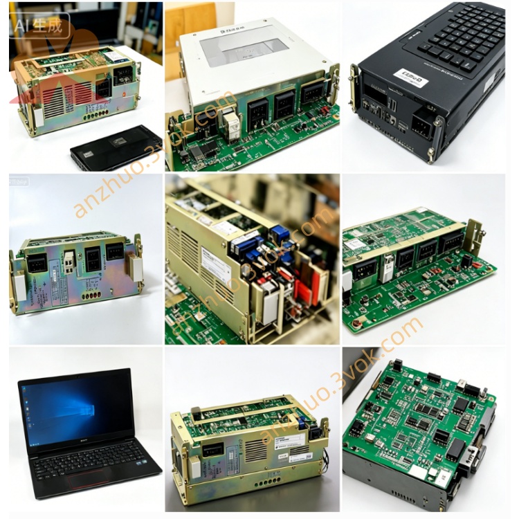
SGDK-75AEA is single-axis CNC dedicated servo amplifier jointly developed by Yaskawa and Siemens on Sigma-II platform, rated power 7.5kW, 200V voltage class, specially matched for Siemens CNC system feed axis control of machine tool equipment. This model belongs to SGDK dedicated CNC servo series, standard non-customized terminal configuration with suffix AEA, widely used for lathe, milling machine and machining center X/Y/Z linear feed axis closed-loop motion control, supporting three mainstream control modes configurable by internal parameters, featuring high overload capacity, stable positioning accuracy and strong anti-interference performance.
Model code definition breakdown: SGDK stands for CNC exclusive servo drive series cooperated by Yaskawa & Siemens; 75 represents rated output capacity 7.5kW; A means three-phase AC200~230V main power input specification; E indicates switchable position/analog speed/analog torque three control modes; final A refers to standard factory standard hardware without customized option board modification, all control interfaces follow official standard pin definition.
Matching servo motor is SGMGH-75A series 7.5kW Sigma-II standard servo motor with 17-bit serial incremental or optional absolute encoder, rated speed 1500rpm for conventional CNC feed application.
2. Detailed Electrical Specification
2.1 Power Parameter
Main circuit input accepts three-phase AC 200V~230V, 50/60Hz power supply, partial low-load scene allows single-phase input with derated continuous output performance. Continuous rated output current of the drive is 54.7A RMS, peak transient overload current reaches 130A within maximum 3 seconds to meet instant heavy cutting impact load of machine tool. Independent external DC24V power supply is available for control circuit to avoid control circuit shutdown caused by main power fluctuation. Cooling mode adopts built-in forced cooling fan for heat dissipation, protection grade IP20, overall net weight around 10.2kg, vertical cabinet mounting design.
2.2 Control Interface & Function Configuration
Equipped with standard CN1 50-pin control connector connecting CNC controller signal, compatible differential line driver and open-collector pulse input for position command, maximum input pulse frequency up to 500kpps with programmable electronic gear ratio to adjust actual feed ratio flexibly. ±10VDC analog voltage input is reserved for speed and torque reference command separately. CN2 single encoder dedicated interface connects motor serial encoder cable, supporting 17-bit serial incremental encoder by default, battery backup absolute encoder is optional for equipment zero point memory after power failure.
Built-in RS485 communication port connects SigmaWin+ parameter debugging software to realize parameter upload/download, real-time running data monitoring, drive self-diagnosis and fault history query. Complete independent closed-loop control logic is adopted inside the unit, with exclusive overcurrent, overvoltage, undervoltage, overheat and encoder abnormal multi-protection function for single axis output channel.
Three configurable working modes: first is pulse position control, the most commonly used mode for CNC feed axis positioning receiving pulse instruction from numerical control system; second is analog speed control relying on ±10V analog signal to realize continuous variable speed running; third is analog torque control applied for tension follow-up or rigid tapping special machining occasion, control mode switching can be completed by modifying corresponding internal parameter codes without hardware wiring change.
3. Environmental & Installation Requirement
Permitted operating ambient temperature ranges from 0 degree Celsius up to positive 55 degree Celsius, storage temperature is from minus 20 degree Celsius to positive 70 degree Celsius. Working environment humidity shall not exceed 90%RH without condensation phenomenon, installation site needs to stay away from corrosive gas, conductive metal dust, oil mist and flammable volatile gas to prevent internal circuit corrosion and short-circuit failure.
Install vertically on rigid metal mounting plate inside electric cabinet, reserve at least 40mm upper and bottom space as well as 30mm left and right clearance for cooling fan air circulation and heat emission. Separate high-power motor power cable and low-voltage signal/encoder cable during wiring layout to reduce electromagnetic interference, all shielded signal cables implement single-side grounding of shielding layer to improve anti-noise capability.
4. Wiring & Commissioning Guidance
Before any wiring operation, disconnect all input AC power and wait more than 15 minutes for internal DC bus capacitor full discharge to prevent electric shock risk from residual stored electricity inside the drive. Main circuit terminals R/S/T connect three-phase AC input power, U/V/W terminals link matched 7.5kW servo motor three power lines, PE grounding terminal must connect reliable equipment protective earth ground strictly. CN1 control cable wiring follows standard SGDK-AEA pin definition, CN2 encoder cable corresponds to motor encoder port one by one without misconnection.
Standard commission steps: firstly finish full wiring inspection to exclude short circuit and wrong connection risk; power on the servo unit to complete built-in self-check and confirm no fault alarm code displayed on front panel indicator; carry out no-load motor automatic tuning to automatically identify motor winding resistance and inductance data, optimize servo system gain parameters; set target control mode, electronic gear ratio, speed upper limit and acceleration/deceleration parameters according to CNC machine design requirement; execute low-speed jog operation without mechanical load to check rotation status, after no abnormal vibration and noise appears, install mechanical load and implement formal linkage debugging with CNC system.
5. Common Fault & Maintenance Instruction
Typical abnormal alarms include overcurrent alarm caused by motor winding short circuit, wrong U/V/W wiring or internal power module damage; encoder error resulting from loose CN2 connector, broken encoder wire or encoder component damage; undervoltage protection triggered by insufficient input power supply voltage or loose main circuit terminal screw; overheat alarm induced by long-time continuous overload, cooling fan stuck or poor cabinet ventilation. After eliminating corresponding fault root cause, cut off total power supply for three minutes then restart equipment to clear fault lockout state, repeated identical fault occurrence requires professional circuit overhaul inspection.
Routine maintenance content: every three months clean cooling fan dust and internal accumulated dirt inside chassis, fasten loose terminal screws to avoid poor contact overheating damage; every half year inspect aging degree of encoder and power cables as well as grounding condition of shielding layer; if the drive is stored for more than 12 months without operation, perform forty minutes no-load pre-running before formal installation to activate internal electrolytic capacitor and restore stable performance.
6. Application Scope
Mainly configured for Siemens series CNC machine tools including numerical control lathe, vertical machining center, grinding machine feed axis drive, also applicable to high-precision automation fixed-length cutting, positioning feeding mechanical equipment requiring stable high-power servo driving, matching Siemens original numerical control system to realize seamless signal docking and high-precision motion linkage control.
Get a Quote