1.Model Code Definition
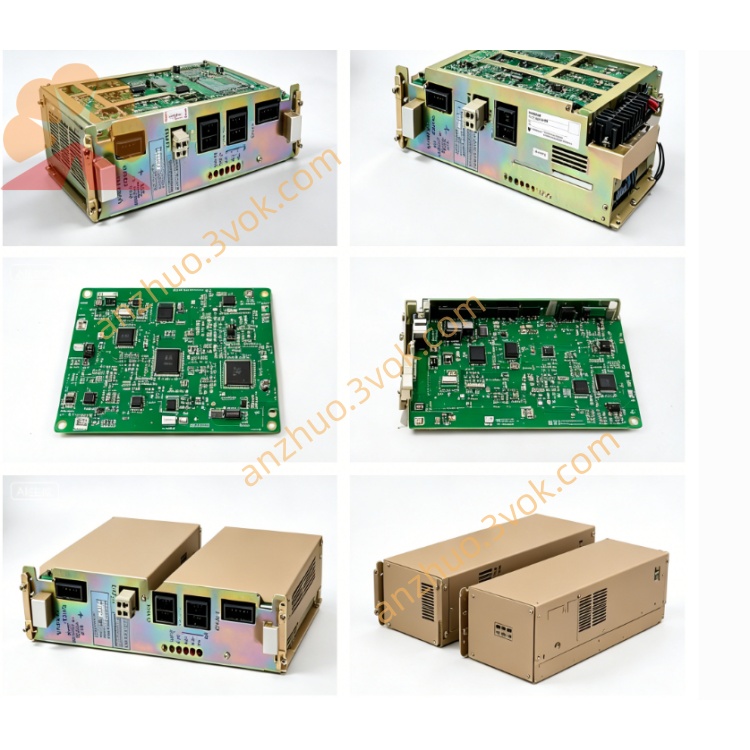
SGDH-A5AEY363 is 50W (0.05kW) OEM customized 200V-class Σ‑II servo amplifier made by Yaskawa Electric
SGDH = Sigma‑II standard servo drive series
A5 = Rated output power: 50W
A = Single/3‑phase AC 200~230V main power input
E = Universal type supporting Position / Analog Speed / Analog Torque three switchable control modes
Y363 = Exclusive OEM customized option board; replaces standard CN1 50pin control connector with dedicated terminal pin definition (non‑standard public wiring, only OEM factory document available for Y363 terminal layout)
Matching Servo Motor: SGMAH‑A5A / SGMPH‑A5A 50W 200V Sigma‑II servo motor
2.Electrical Specifications
2.1 Power Rating
Main circuit input: Single/3‑phase AC 200~230V, 50/60Hz
Rated continuous output current:
0.64A RMS; peak transient output current: 2.0A (max 3 seconds)
Three‑phase adjustable output voltage: 0~AC230V
Independent external DC24V ±10% power supply for control circuit
Cooling: Natural convection (no built‑in cooling fan), protection grade IP20; net weight approx 0.58kg
2.2 Control Specifications
Three working modes configurable via internal parameters:
Pulse train position control (differential / open‑collector pulse input, max input frequency 500kpps, programmable electronic gear ratio)
±10VDC analog speed control
±10VDC analog torque control
Y363 custom board feature: Abolishes original standard CN1 pin assignment; all servo enable, fault alarm output, command pulse, analog reference and digital I/O signals are routed to dedicated screw terminals on Y363 expansion board, wiring specification follows exclusive OEM custom drawing instead of standard SGDH manual definition.
CN2 encoder port remains standard: compatible with 17‑bit serial incremental encoder; battery backup absolute encoder optional.
Built‑in RS485 communication interface for SigmaWin+ software parameter setup, auto‑tuning and monitoring; Y363 occupies option slot with no spare expansion space for extra fieldbus cards.
Integrated automatic motor identification function for winding resistance/inductance detection and servo gain auto tuning.
2.3 Environmental Conditions
Operating ambient temperature: 0℃ ~ +55℃; storage temperature: −20℃ ~ +70℃
Working humidity ≤90%RH without condensation; install in environment free of corrosive gas, flammable dust and liquid splash
Allowable vibration: 10~55Hz, acceleration ≤0.5G
3.Installation Instruction
Mount vertically on rigid metal base plate; reserve ≥30mm clearance top/bottom, ≥20mm clearance left/right for heat dissipation.
Keep away from heat source and direct sunlight; fasten mounting screws tightly against runtime vibration.
Separate high‑power motor cable and low‑voltage Y363 signal/encoder cable during wiring to reduce EMI; single‑end grounding for all signal cable shielding layers.
4.Wiring & Commissioning Guide
Cut all input power and wait minimum 10 minutes for internal DC bus capacitor full discharge before opening cover or modifying wiring to avoid electric shock hazard.
Main terminals R/S/T (single‑phase use L1/L2) connect AC200~230V input; U/V/W connect three leads of matched 50W servo motor; PE terminal must connect reliable equipment protective ground.
All wiring for Y363 custom terminals strictly comply with OEM exclusive wiring document, not standard CN1 wiring rules.
Double check power and Y363 signal wiring before power‑on
Power up drive, complete self‑diagnosis and confirm no hardware fault alarm
Perform no‑load motor auto‑tuning to match drive and motor parameters automatically
Set control mode and relevant function parameters plus Y363 dedicated custom parameters as per machine manufacturer requirement
Execute low‑speed jog test without load before formal loaded operation
5.Fault Diagnosis & Troubleshooting
Overcurrent alarm: Caused by motor winding short circuit, damaged power cable or wrong U/V/W wiring; power off to inspect cable insulation and motor coil
Encoder error: Loose CN2 connector, broken encoder wire or wrong Y363 feedback terminal wiring; replace defective wire and rewire accordingly
Undervoltage alarm: Insufficient input voltage or unstable power source capacity
Overheat alarm: Long‑term continuous overload or poor ventilation; reduce actual load and improve ambient heat dissipation
Clear fault by full power cycle after eliminating abnormal cause; send to professional repair if same fault repeats continuously.
6.Routine Maintenance
Clean accumulated dust inside drive every 3~6 months according to site dust level; regularly retighten loose terminal screws to avoid poor contact overheating damage.
For long‑term idle storage over 12 months, carry out 30‑minute no‑load pre power‑on test before installation and commissioning.
7.Manual Supplement Note
Standard English general manual No.SIEPS80000005A covers base SGDH‑A5AE specification, but Y363 customized terminal definition has no public official English document, need to obtain exclusive Y363 wiring sheet from original equipment OEM manufacturer.
Get a Quote