SGDH-A1BEY195
Description
1.Model Definition
SGDH = Σ-II servo amplifier series
A1 = Rated power 100W (0.1kW)
B = Single-phase AC100V input specification
E = Universal drive supporting Position / Analog Speed / Analog Torque three control modes
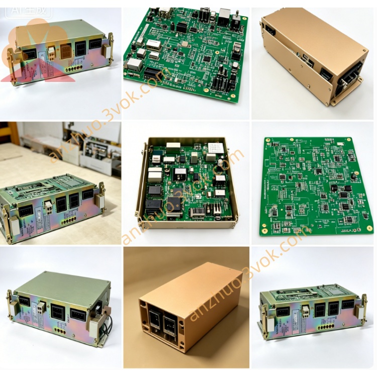
Y195 = Factory exclusive customized option board, replaces standard CN1 50pin control connector with dedicated terminal wiring definition (non-standard public pinout, OEM exclusive drawing only)
2.Basic Electrical Parameters
3.Control Function Description
4.Installation & Wiring Rules
5.Commissioning Procedure
Double-check all power and Y195 signal wiring correctness before power on.
Power up the drive, complete self-diagnosis, confirm no hardware fault alarm.
Execute motor no-load auto-tuning to match drive and motor parameters automatically.
Set target control mode and related functional parameters, configure Y195 exclusive custom parameters per machine OEM requirement.
Perform low-speed jog test without load first, then formal loaded running after normal jog operation.
6.Common Fault & Troubleshooting
Overcurrent alarm: Caused by motor coil short, damaged power cable or wrong U/V/W wiring; power off and inspect cable insulation and motor winding.
Encoder error: Result from loose CN2 connector, broken encoder wire or incorrect Y195 feedback terminal wiring; replace defective cable and rearrange wiring.
Undervoltage alarm: Caused by insufficient input voltage or unstable power source supply capacity.
Overheat alarm: Triggered by long-time continuous overload or poor ambient ventilation; reduce actual load and improve surrounding heat dissipation.
Clear fault by full power off & restart after fault root cause is fixed; send to professional maintenance if same alarm repeats frequently.
Get a Quote