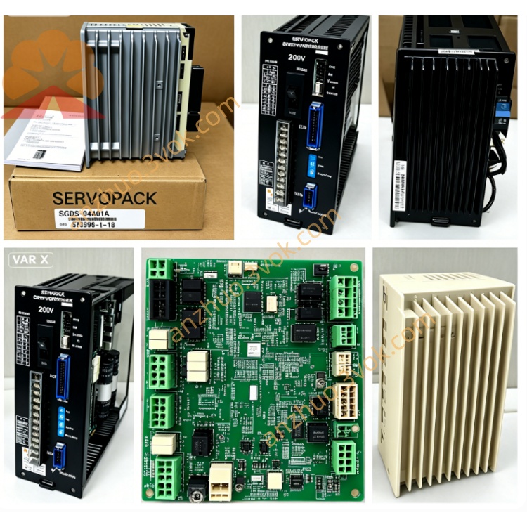
SGDH-50AE-RY415
SGDH-50AE-RY415 is a customized 5.0kW AC servo amplifier of Yaskawa Sigma-II series.
Model code explanation:
SGDH = Sigma-II standard servo drive platform;
50 = Designed for 5.0kW matched servo motor;
A = Single/three-phase AC 200V~230V power input specification;
E = Universal type supporting position, speed and torque three switchable control modes;
RY415 = OEM customized optional board which replaces standard CN1 control interface with exclusive non-standard terminal definition for special pulse input and digital I/O signals.
Description
1. Product Overview
SGDH-50AE-RY415 is a customized 5.0kW AC servo amplifier of Yaskawa Sigma-II series.Model code explanation:SGDH = Sigma-II standard servo drive platform;50 = Designed for 5.0kW matched servo motor;A = Single/three-phase AC 200V~230V power input specification;E = Universal type supporting position, speed and torque three switchable control modes;RY415 = OEM customized optional board which replaces standard CN1 control interface with exclusive non-standard terminal definition for special pulse input and digital I/O signals.
Applicable matched motors include SGMGH-50A, SGMAH-50A and SGMPH-50A 5.0kW 200V Sigma-II servo motors.
2. Electrical Specifications
2.1 Power Rating
Rated matching motor power: 5.0kWMain circuit input: Single/3-phase AC 200~230V, 50Hz/60Hz, rated input current 32.8AContinuous rated output current: 32.9A RMS; peak transient output current:79A within maximum 3 secondsThree-phase output adjustable AC voltage: 0~230VExternal independent DC24V ±10% power supply is required for control circuit operationCooling method: Forced air cooling with built-in cooling fan, IP20 protection gradeNet weight is approximately 6.8kg
2.2 Control Specification
Three control modes including pulse position control, ±10VDC analog speed control and ±10VDC analog torque control can be switched via internal parameter setting.Standard base drive supports differential or open-collector pulse position command with maximum input frequency up to 500kpps and programmable electronic gear ratio.RY415 customized board cancels original standard CN1 pin assignment, provides exclusive dedicated pulse receiving port and isolated multi-channel digital input/output terminals for special mechanical interlock and signal interaction, whose wiring definition follows OEM factory custom specification instead of general standard manual.Encoder interface is compatible with 17-bit serial incremental encoder; battery-backed absolute encoder is available as optional configuration.Built-in RS485 communication port is reserved for SigmaWin+ software parameter reading and modification; RY415 occupies original standard fieldbus expansion space without universal bus slot.Auto motor tuning function is integrated to automatically identify motor winding resistance, inductance and encoder offset for servo gain optimization.
2.3 Environmental Conditions
Operating ambient temperature: 0℃ ~ +55℃; storage temperature: -20℃ ~ +70℃Relative working humidity ≤90%RH without condensation; installation environment must avoid corrosive gas, combustible dust and liquid splashingAllowable operating vibration: 10~55Hz with vibration acceleration no higher than 0.5G
3. Installation Instructions
Mount the servopack vertically on rigid metal mounting plate. Keep more than 35mm clearance at top and bottom, and over 25mm gap on left and right sides for heat dissipation.Keep away from direct sunlight and surrounding heat sources; tighten mounting screws firmly to prevent looseness caused by equipment runtime vibration.Separate high-power motor cables and shielded control/encoder/RY415 signal cables during wiring construction to reduce electromagnetic interference; single-end grounding for all shield layers of signal cables.
4. Wiring & Commissioning Guidance
Cut off all input power and wait at least 10 minutes for internal high-voltage DC bus capacitor full discharge before casing opening, wiring change or maintenance to prevent electric shock accident.Main circuit terminals R/S/T connect AC200~230V power source; U/V/W terminals link three-phase leads of matched 5.0kW servo motor; PE grounding terminal must connect reliably to equipment common grounding bus.All pulse and I/O wiring related to RY415 option card shall comply with OEM exclusive customized terminal definition rather than standard CN1 wiring rules.Double-check all wiring correctness before power-on; execute no-load motor auto-tuning after drive self-check finishes. Set control mode and relevant functional parameters as well as exclusive RY415 customized parameters accordingly. Perform low-speed no-load jog test first before formal loaded operation.
5. Fault Diagnosis & Troubleshooting
Overcurrent alarm is generally caused by motor winding short-circuit, damaged power cable or wrong main circuit wiring; cut off power and inspect wire insulation and motor coil status.Encoder fault results from loose connector, broken encoder cable or mismatched wiring on RY415 customized terminals; replace defective cable or rearrange wiring after fault confirmation.Undervoltage alarm occurs due to excessive input voltage drop or insufficient capacity of power supply.Overheat alarm is triggered by blocked cooling air duct, damaged cooling fan or long-time continuous overload; clean accumulated dust and reduce practical operating load.Reset fault status by complete power cycle after eliminating abnormal trigger factors; arrange professional repair if identical fault repeats continuously.
6. Routine Maintenance
Clean cooling fan and internal dust every 3~6 months based on on-site environmental dust density; regularly retighten loose terminal screws to avoid poor-contact overheating failure.Store the unit in dry sealed environment for long-term idle placement; carry out 30-minute no-load power-on pre-test before installation and commissioning if storage period exceeds 12 months.
7. Application Range
Customized CNC machine feed axes, special precision automation processing equipment, dedicated packaging machinery and special automation production equipment requiring RY415 customized control interface configuration.
Get a Quote