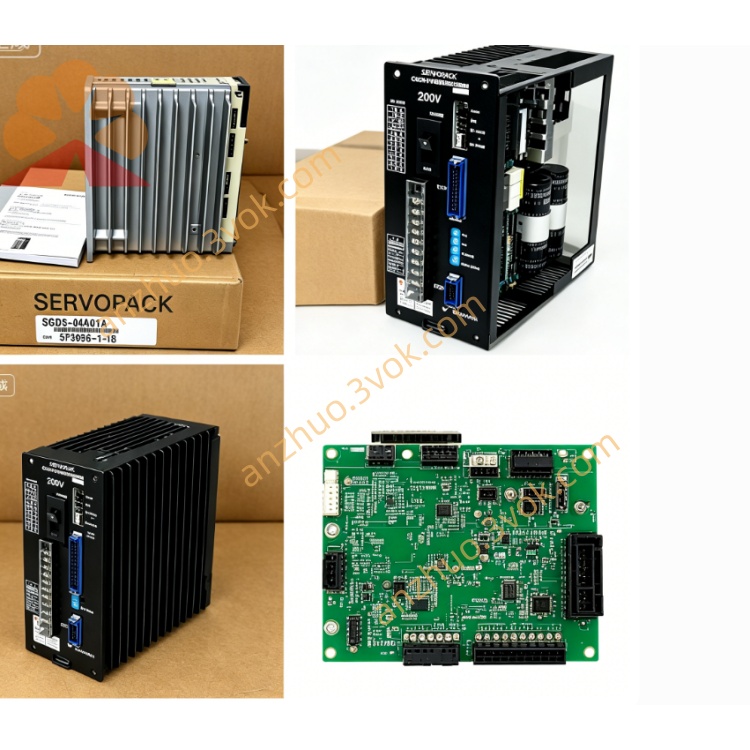
SGDH-30AE-RY416
Description
1. Model Code Explanation & Overview
SGDH: Standard Sigma-II Servopack drive platform
30: Rated matching motor power = 3.0kW (3000W)
A: Input specification: Single/3-phase AC200~230V ±10%, 50/60Hz (200V low voltage grade)
E: Universal base unit supporting switchable Position / Speed / Torque three core control modes
RY416: OEM customized dedicated option card for special pulse command interface, customized multi-channel I/O and proprietary controller docking (unique pin definition different from standard CN1 port, dedicated for special CNC & automation equipment)
2. Key Electrical Specifications
2.1 Power Parameters
Rated applicable motor output: 3.0kW
Main circuit input: 1Φ/3Φ AC200~230V, 50/60Hz; rated input current:17.0A
Continuous rated output current:24.8A RMS; peak transient output:59.5A (max 3 seconds)
3-phase output:0~230VAC, output frequency range:0~300Hz
Independent auxiliary control power: External DC24V ±10% required for control circuit power supply
Cooling: Built-in axial cooling fan forced convection cooling; IP20 cabinet protection grade
Net weight: Approx.3.8kg; dimension: H250 × W110 × D180mm
2.2 Control & RY416 Extended Functions
Standard three adjustable control modes: Pulse Position / Analog Speed / Analog Torque via parameter setup
Standard position input: Differential/open-collector pulse signal, max input frequency up to 500kpps, programmable electronic gear ratio
RY416 exclusive added features: Special extended command port for high-speed external controller pulse input, customized isolated digital input/output terminals for equipment synchronous interlock, dedicated serial signal conversion for special encoder connection (replaces partial standard CN1 interface functions with OEM fixed pin assignment)
Analog reference input: ±10VDC analog signal for speed/torque instruction
Encoder compatibility: Default 13-bit incremental encoder; optional battery-backed absolute encoder connection
Communication: Built-in RS485 for SigmaWin+ servo debugging software; RY416 reserves dedicated proprietary communication channel instead of standard fieldbus slot
Onboard algorithms: Full automatic motor parameter identification, auto gain tuning, mechanical vibration suppression function
3. Environmental Specification
Operating ambient temperature:0℃~+55℃; storage temperature:−20℃~+70℃
Working humidity: ≤90%RH non-condensing, no corrosive gas, conductive dust or liquid splash
Vibration endurance:10~55Hz, vibration acceleration ≤0.5G
4. Installation & Wiring Requirements
Vertical cabinet panel mounting; reserve ≥35mm top/bottom clearance and ≥25mm left/right spacing for heat dissipation.
Cut off all AC input power and wait minimum 10 minutes for internal DC bus capacitor complete discharge before wiring or maintenance to avoid high-voltage shock hazard.
Main terminals R/S/T connect AC200~230V input power; U/V/W terminals link three-phase servo motor winding; PE protective terminal must connect reliably to cabinet grounding bar.
Separate high-power motor cable and shielded control/encoder/RY416 signal wiring to minimize EMI interference; all shield signal cables implement single-end grounding.
RY416 port wiring strictly follows OEM customized pin definition (non-standard CN1 pinout, refer to RY416 option card exclusive manual).
5. Standard Commissioning Steps
Complete full wiring inspection to exclude short circuit, reversed wiring or loose terminals before power-on.
Power on to finish drive self-diagnosis; run no-load auto-tuning to automatically read motor resistance, inductance and encoder parameters.
Configure target control mode via internal parameters; set electronic gear ratio for position mode or speed/torque loop gain accordingly, plus RY416 dedicated function parameters.
Execute low-speed no-load jog test first; switch to formal loaded operation after stable running without alarm.
6. Common Fault Troubleshooting
OC Overcurrent Alarm: Check motor U/V/W winding short-circuit, damaged power cable or incorrect main circuit wiring
Encoder Fault: Inspect loose encoder plug, broken shield wire or mismatched RY416 signal wiring
UV Undervoltage Alarm: Input AC200V voltage drop or insufficient power source capacity
OH Overheat Alarm: Damaged cooling fan, blocked ventilation opening or continuous overload; clean internal dust and reduce mechanical load
Fault reset: Full power cycle after fault root cause is eliminated.
7. Periodic Maintenance Rules
Clean cooling fan and internal accumulated dust every 3~6 months based on site environment; regularly retighten loose power terminal screws.
For storage longer than 12 months, perform 30-minute no-load preheating power-on before formal commissioning.
Get a Quote