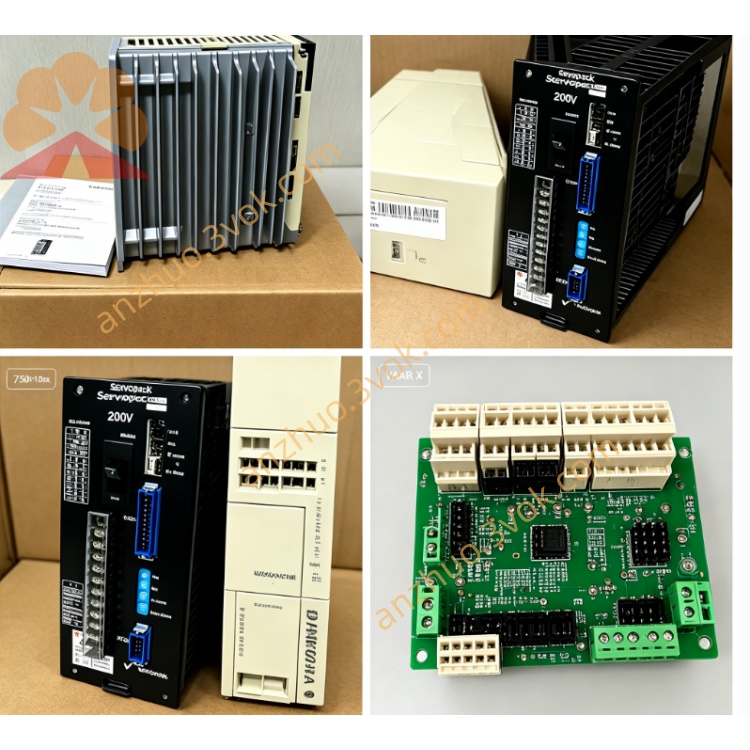
SGDH-08AE
Description
1. Product Introduction
Model coding definition:
SGDH = Sigma II standard servo amplifier platform
08 = Rated power class for 0.75kW (750W) matching servo motor
A = AC200V~230V single/3-phase main power input specification
E = Universal type supporting switchable Position / Speed / Torque three control modes
Matched motor series: SGMAH, SGMPH, SGMAS 750W 200V Sigma‑II servo motors.
2. Electrical Specifications
2.1 Power Parameter
Rated applicable motor power: 0.75kW (750W)
Main input voltage: Single-phase or 3‑phase AC200~230V (±10%), 50/60Hz
Continuous rated output current: 5.7A RMS; Peak short-time output current:13.9A (max 3s)
Output: 3‑phase 0~230VAC, output frequency range:0~300Hz
Control power: External DC24V auxiliary power supply required
Cooling mode: Built-in cooling fan forced air cooling
2.2 Control Functions
Three optional control modes: Pulse Position / Analog Speed / Analog Torque, switched via internal parameter setup
Position command: Differential/open-collector pulse input, maximum input frequency up to 500kpps; programmable electronic gear ratio
Analog reference signal: ±10VDC for speed or torque command input
Encoder interface: Compatible with 13-bit serial incremental encoder; auto motor parameter identification after power-on
Communication: Standard RS485 serial port for SigmaWin+ debugging software; optional MECHATROLINK‑I/II, DeviceNet fieldbus expansion card slots
Speed response bandwidth: 300Hz standard, adjustable by auto-tuning function
Built-in regenerative brake circuit for dynamic braking without external brake resistor in regular load conditions
2.3 Environmental & Dimension
Operating ambient temperature: 0℃ ~ +55℃; Storage temperature:−20℃ ~ +70℃
Humidity: ≤90%RH non-condensing, no corrosive gas, explosive dust or liquid splash
Anti-vibration: 10~55Hz, vibration acceleration ≤0.5G
Outer dimension: H150 × W80 × D140 mm; Net weight approx.1.1kg
3. Installation & Wiring Rules
Vertical mounting on metal base or DIN rail; reserve ≥30mm top/bottom and ≥20mm left/right gap for heat dissipation.
Cut off all power and wait over 10 minutes for internal DC bus capacitor full discharge before wiring or maintenance to avoid electric shock.
Main circuit terminals R/S/T connect AC220V input; U/V/W connect three-phase terminals of matched 750W servo motor; reliably ground PE protective terminal.
Separate high-power motor cable and shielded encoder/control signal cable to reduce EMI interference; shield layer of encoder cable single-end grounded.
4. Commissioning Steps
Complete full wiring inspection to exclude short circuit or wrong connection before power-on.
Power on for drive self-diagnosis; execute no-load auto-tuning to automatically identify motor winding and encoder parameters.
Select target control mode by parameter modification; set electronic gear ratio for position mode or speed loop gain for analog control mode.
Implement low-speed jog no-load test first; switch to formal loaded operation after stable trial run.
5. Common Fault & Troubleshooting
OC Overcurrent Alarm: Check motor U/V/W short circuit, broken winding or wrong power wiring
Encoder Error: Inspect loose encoder connector, damaged shield cable or mismatched wiring sequence
UV Undervoltage Alarm: Abnormal AC220V input voltage drop or insufficient power source capacity
OH Overheat Alarm: Fan failure, blocked air vent or long-term continuous overload; clean dust and reduce mechanical load
Clear fault by power off and restart after eliminating root failure cause.
6. Periodic Maintenance
Clean fan and internal dust every 3~6 months per working environment; retighten loose terminal screws regularly.
For long-term storage over 12 months, perform 30min no-load preheating power-on before on-site commissioning.
Get a Quote