SGDH-05DE
Description
1. Product Overview
SGDH = Sigma II standard servo drive platform
05 = 0.5kW rated power
D = 3‑phase 400VAC main power input specification
E = universal model supporting Position / Speed / Torque three switchable control modes
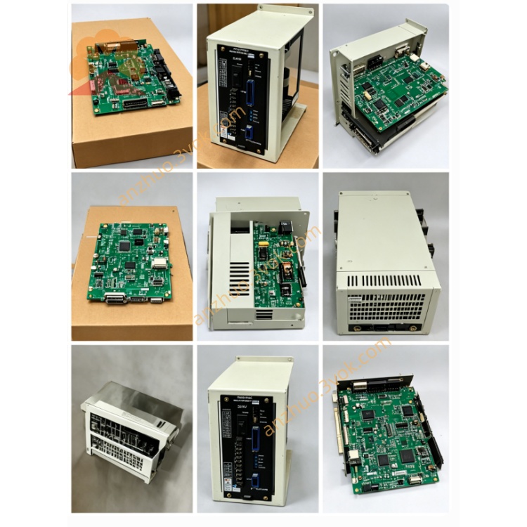
It is discontinued legacy industrial servo, widely matched with SGMGH‑05D, SGMSH‑05D series 400V Yaskawa servo motors for automation equipment.
2. Electrical Specifications
2.1 Power Ratings
Rated applicable motor power: 0.5kW
Main power supply: Three‑phase AC380~480V (±10%), 50/60Hz
Continuous rated output current: 3.5A; Peak instantaneous output current:10.5A
Control power: Built‑in internal auxiliary power from main input
Cooling: Natural air cooling, IP20 enclosure rating
2.2 Control Features
Three configurable control modes: Position / Analog Speed / Analog Torque, switch via parameter setting
Position command: Differential/open‑collector pulse input, max input frequency 500kpps; electronic gear ratio programmable
Analog command: 0~±10VDC for speed/torque reference signal input
Encoder interface: Support 17‑bit incremental encoder; absolute encoder available with external backup battery
Communication: Standard RS485 serial port (Yaskawa drive protocol, compatible with SigmaWin+ software for parameter upload/download); optional fieldbus expansion card slot
Speed response bandwidth: Up to 1.5kHz for high dynamic response
2.3 Environmental Conditions
Operating ambient temperature: 0℃ ~ +55℃; Storage: −20℃ ~ +70℃
Relative humidity: ≤90%RH non‑condensing, no corrosive gas, dust or liquid splash
Vibration resistance: 10~55Hz, ≤0.5G acceleration
3. Installation & Wiring Rules
Mount vertically on DIN rail or metal base plate; reserve ≥30mm upper/lower and ≥20mm left/right clearance for heat dissipation.
Cut off main power and wait at least 10 minutes for internal bus capacitor full discharge before any wiring maintenance.
Main circuit terminals R/S/T connect three‑phase 400V input; U/V/W connect matched servo motor three‑phase winding; ground PE terminal reliably to equipment protective earth bar.
Separate high‑power motor cables and shielded encoder/control signal cables to reduce EMI interference; encoder cable must use shielded dedicated wiring with grounded shield end.
Control I/O terminal definition follows standard Sigma‑II E‑type manual pinout.
4. Commissioning Steps
Complete full wiring inspection before power energization, confirm no short circuit or reversed polarity.
Power on for self‑diagnosis; execute no‑load auto motor tuning to identify motor coil & encoder parameters automatically.
Select required control mode via parameter, set electronic gear ratio (position mode) or analog gain parameters (speed/torque mode).
Perform low‑speed no‑load jog test first; switch to formal loaded operation after stable trial running.
5. Fault Troubleshooting
Overcurrent Alarm (OC): Check motor U/V/W short circuit, winding damage or wrong wiring connection.
Encoder Error: Inspect loose encoder connector, broken shield cable or mismatched wire sequence.
Main Circuit Undervoltage (UV): Abnormal 400V input voltage drop, insufficient input power source capacity.
Overheat Alarm (OH): Poor ventilation, blocked cooling vent or continuous long‑term overload; clean dust and reduce mechanical load.
Reset fault by power cycle after eliminating failure root cause.
6. Regular Maintenance
Clean surface dust every 3~6 months according to site environment; retighten loose terminal screws periodically.
For storage over 12 months, run 30min no‑load preheating before on‑site commissioning.
Get a Quote