SGDF-B5CP
Description
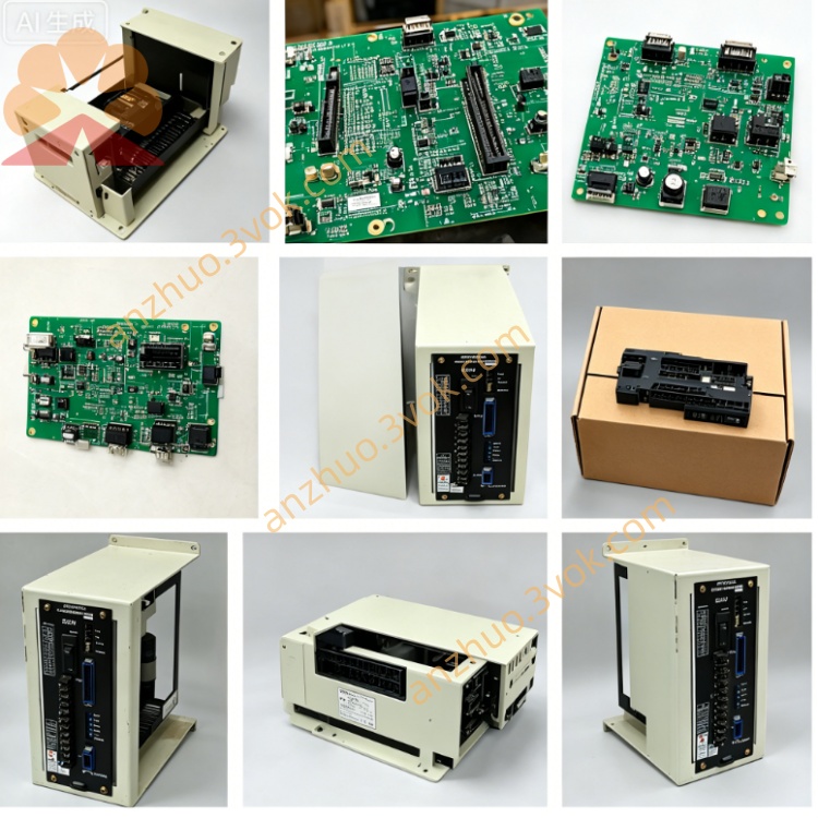
1. Product Overview
2. Electrical Specifications
2.1 Power Ratings
Matched motor rated power: 5W
Main power supply input: DC24V, rated input current 2.9A
Three-phase output: adjustable low-voltage AC for 5W miniature servo motor
Cooling type: passive natural heat dissipation without built-in cooling fan
Certification: CE compliant
2.2 Control Configuration
Control mode fixed as Pulse Position Control only (no analog speed/torque control available per CP customization)
Command input: open-collector or differential pulse train positioning signal from upper controller
Encoder interface: dedicated connector for incremental encoder paired with SGMM-B5C servo motor
Debug interface: ERSPRO dedicated network port for parameter upload/download via Yaskawa official debugging software
I/O terminals: CP customized pin assignment deviates from standard SGDF-B5C wiring definition, strictly follow factory custom wiring document for terminal layout
2.3 Environmental Conditions
Operating ambient temperature: 0°C ~ +55°C; storage temperature: -20°C ~ +70°C
Relative humidity: ≤90% RH without condensation; avoid corrosive gas, combustible dust and liquid splashing
Vibration resistance: 10~55Hz, maximum vibration acceleration ≤0.5G
3. Installation Instructions
Mount the servopack vertically onto solid metal DIN rail or mounting plate.
Keep clearance ≥30mm at top/bottom and ≥20mm on left/right for heat dissipation.
Install away from heat source and direct sunlight; fasten mounting screws tightly against mechanical vibration loosening.
Separate power cables and shielded control/encoder cables during wiring layout to reduce electromagnetic interference; connect PE grounding terminal reliably to equipment grounding bus.
4. Wiring Requirements
Cut off DC24V power supply and wait minimum 5 minutes for internal capacitor full discharge before wiring or maintenance to prevent electric shock hazard.
DC24V positive/negative polarity must not be reversed; reverse connection will permanently damage internal circuit.
Motor power terminals U/V/W connect to corresponding three-phase leads of matched 5W servo motor; secure encoder dedicated shielded cable connector tightly.
All position pulse input and digital I/O wiring shall comply with CP customized terminal drawing instead of standard SGDF series manual definition.
5. Commissioning Procedure
Double-check all wiring correctness before DC24V power-on for drive self-inspection.
Complete no-load motor parameter auto-tuning after power initialization to automatically identify motor winding and encoder parameters.
Set electronic gear ratio parameters according to required positioning resolution.
Perform no-load jog operation test first; switch to low-load formal operation after stable no-load running.
6. Fault Diagnosis & Troubleshooting
Overcurrent Alarm: Power off and check short-circuit of motor U/V/W cable or damaged motor winding.
Encoder Fault: Inspect loose connector, broken encoder cable or mismatched CP customized wire sequence.
Undervoltage Alarm: Caused by insufficient DC24V power capacity or excessive voltage drop on power line.
Overheat Alarm: Blocked heat sink or continuous overload; clean surface dust and reduce machine load.
Reset fault by power cycle after eliminating fault root cause; contact professional maintenance if same alarm repeats continuously.
7. Periodic Maintenance
Clean surface dust every 3~6 months based on on-site working environment; retighten loose terminal screws regularly.
For long-term storage over 12 months in dry sealed environment, conduct 30-minute no-load power-on pre-test before field commissioning.
Get a Quote