JANCD-SPI17B
Description
1. General Information
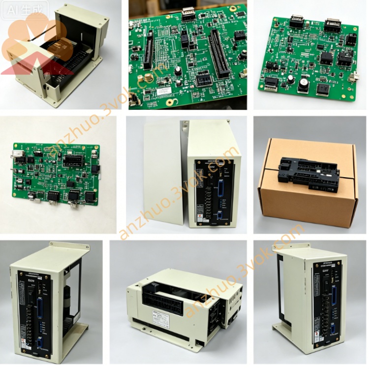
Part Number: JANCD-SP17B, DF8203304-B0
Manufacturer: Yaskawa Electric / Motoman Robotics
Product Type: CRT and MDI display control board
Core Functions: Monochrome CRT driving, keyboard signal processing, front panel I/O and status LED control, data communication with main controller
Applicable Systems: Early versions of YASNAC LX / MX CNC systems and Motoman ERC robot controllers, matched with monochrome CRT operator panels
Product Status: Discontinued. Only used and refurbished units are available on the market
Product Position: A legacy interface board, serving as the earlier model of JANCD-SP20 series
2. Technical Specifications
Electrical Parameters
Power Supply: +5 V DC and +12 V DC from the system backplane
Maximum Current Draw: Approximately 1.2 A
Video Signal: Monochrome CRT output signal
Environmental Parameters
Operating Temperature: 0 °C to 45 °C
Storage Temperature: -20 °C to 60 °C
Relative Humidity: 5% to 85%, non-condensing
Physical Parameters
Mounting Form: Standard plug-in card for Yaskawa backplane slot
Weight: About 0.95 kg
3. Main Functions
- CRT Display ControlIt provides driving and timing signals for monochrome CRT monitors, and outputs system text content, running status, alarm codes and parameter information to the display screen.
- Keyboard Signal ProcessingScans the key matrix of the external keypad, completes signal debounce and code conversion, and transmits valid operation commands to the main control unit.
- Front Panel I/O ManagementProcesses signals from panel mode switches and physical buttons, and drives multiple LED indicators to display power status, system operation and fault alerts.
- System Data CommunicationActs as a data transmission bridge between the human-machine panel and the main controller, realizing two-way data interaction.
4. Compatibility
Compatible Devices
Early YASNAC LX, MX series CNC controllers
Early revision Motoman ERC robot controllers
Supporting monochrome CRT monitor and matched keypad
Incompatible Devices
XRC, NX100, DX series and other new-generation Motoman robot controllers
SP20C, SP21, SP23 and other later upgraded interface boards
5. Installation Steps
Cut off the total power of the controller and wait at least 5 minutes for the internal capacitors to fully discharge.
Wear an anti-static wrist strap to prevent static electricity from damaging electronic components.
Align the board with the designated slot on the backplane and insert it firmly, then tighten the fixing screws.
Connect the CRT video cable and keypad connecting cable to the corresponding interfaces on the board.
Restore the system power supply, then check the display effect, keypad response and LED status to confirm normal operation.
6. Troubleshooting
No display on CRT monitor
Keypad fails to respond
LED indicators do not light up
System cannot detect the board
7. Maintenance and Safety Notes
Always cut off the power supply before disassembling, inspecting or replacing the board.
Static protection measures must be taken during all handling procedures.
Do not plug or unplug any connecting cables when the system is powered on.
Keep the board and connectors clean, away from dust, moisture and corrosive substances.
Conduct regular inspection on cables and connectors to avoid poor contact caused by aging or wear.
Get a Quote