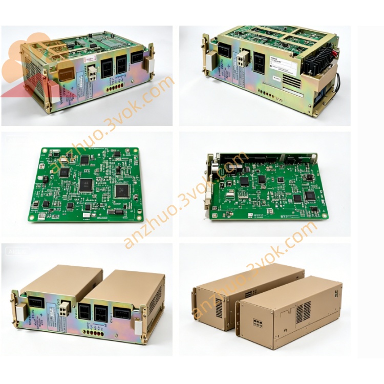
JANCD-SP02 LCD Display & Operator Interface Board
Description
1. General Information
1.1 Overview
1.2 Basic Information
Model: JANCD-SP02
Part Number: DF8201105
Manufacturer: Yaskawa Electric / Motoman
Applicable Device: Motoman XRC robot controller
Board Type: LCD display & operator interface PCB
Product Status: Discontinued, only used and refurbished units available
Weight: Approximately 0.48 kg
Origin: Japan
2. Electrical and Environmental Specifications
2.1 Power Supply
Input Voltage: 5 VDC ±5% (supplied by controller backplane)
Rated Current: 100 mA (nominal)
Max Power Consumption: Less than 0.5 W
2.2 Interface Parameters
Main Interface: Dedicated port for XRC built-in LCD module
Auxiliary Parts: Integrated signal circuits for panel LEDs and push buttons
Signal Type: Digital video and control signals
2.3 Environmental Conditions
Operating Temperature: 0 °C to 40 °C
Storage Temperature: -20 °C to 50 °C
Relative Humidity: 5% to 80%, non-condensing
Maximum Operating Altitude: 1000 meters above sea level
3. Main Functions
- LCD Display DrivingTransmits system data to the front LCD screen to display robot operating mode, servo status, alarm codes, program information and I/O status.
- Local Operation ControlReceives signals from physical push buttons on the controller panel to realize basic operations including mode switching, program start/stop and alarm reset.
- Status IndicationBuilt-in multiple LED indicators to show power supply state and data communication activity for quick on-site inspection.
- Internal Bus CommunicationExchanges data and commands with the main control board of XRC controller via internal bus, acting as a bridge between human-machine interface and system CPU.
4. Compatibility and Installation
4.1 Compatibility
4.2 Installation Steps
Cut off the main power of the controller and wait at least 5 minutes for internal capacitors to fully discharge.
Wear an ESD wristband to prevent static damage to electronic components.
Insert the board into the designated slot on the XRC backplane and fix it firmly.
Connect the matching cables to the front LCD module and button panel.
Restore power supply, then check if the LCD screen and panel indicators work normally.
5. Maintenance and Safety Precautions
Conduct regular inspection every 3 months. Check all cables and connectors for looseness, dust or oxidation.
Use only dry lint-free cloth for cleaning. Do not use liquid detergent or compressed air with high pressure.
Static electricity may damage circuit components. Always take ESD protection measures when handling the board.
Disconnect all power before disassembly, inspection or replacement.
All installation, maintenance and repair work must be performed by qualified professional technicians.
6. Troubleshooting
| Fault Phenomenon | Possible Cause | Solution |
|---|---|---|
| LCD screen no display | Loose cable or poor connection | Reconnect and fasten all cables |
| Panel buttons fail to respond | Faulty button signal circuit | Check board and wiring status |
| All indicators stay off | Abnormal 5V power supply | Inspect controller backplane power circuit |
| Board cannot be recognized by system | Improper insertion | Reinstall the board tightly into the slot |
Get a Quote