JANCD-SP01
Description
1. General Information
1.1 Overview
1.2 Basic Specifications
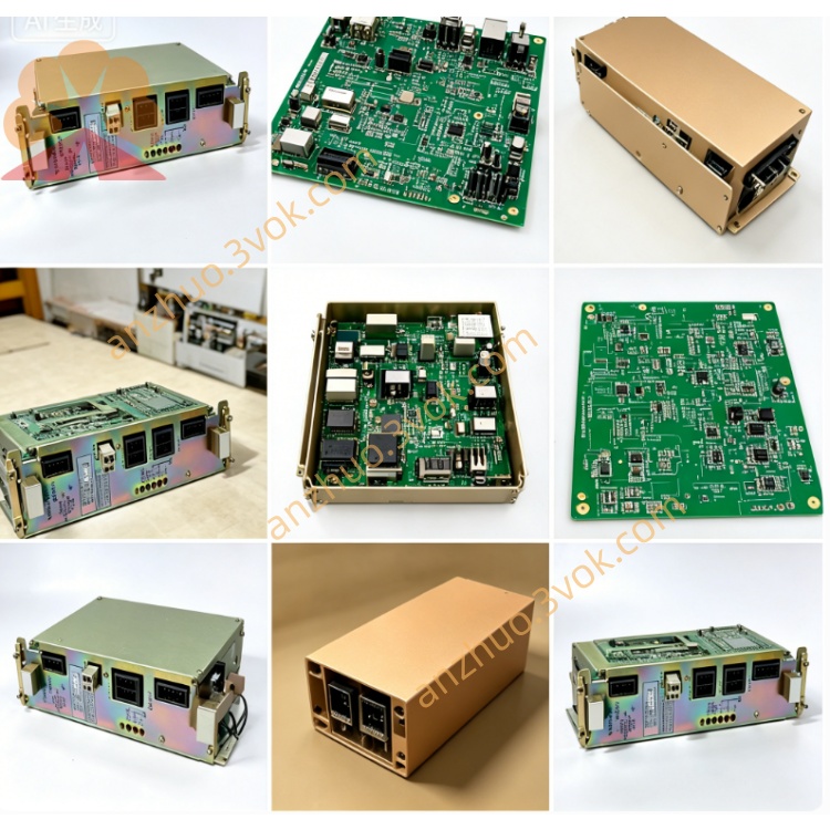
Model: JANCD-SP01 (also DF8000048)
Manufacturer: Yaskawa Electric / Motoman
System: Motoman XRC Robot Controller
Board Type: Serial Communication PCB
Status: Discontinued (used/refurbished only)
Weight: ~0.45 kg (0.99 lbs)
Origin: Japan
2. Interface & Electrical
2.1 Communication Ports
Channel 1: RS-232 (D-Sub 9-pin)
Channel 2: RS-422 / RS-485 (terminal block)
Protocol: Asynchronous (ASCII, MODBUS RTU, etc.)
Baud Rate: 300–115.2 kbps
Data Bits: 7 / 8
Parity: None / Odd / Even
Stop Bits: 1 / 2
2.2 Electrical
Power: 24 VDC ±10% (from backplane)
Power Consumption: ~8 W max
Isolation: RS-422/485 side isolated
2.3 Environment
Operating Temp: 0 °C to +40 °C
Storage Temp: -20 °C to +50 °C
Humidity: 5%–80% RH (non-condensing)
3. Functions
- Serial Data Exchange
Connect robot to external devices via RS-232/422/485.
Support for MODBUS RTU (master/slave).
- Program Upload/Download
Back up/restore robot programs and parameters via RS-232.
- External Device Control
Read barcode scanners, weigh scales, or process instruments.
Send/receive ASCII strings for custom protocols.
- Diagnostics
TX/RX LEDs per channel for quick cable/activity check.
4. Compatibility & Installation
4.1 Compatibility
Only: Motoman XRC series controllers
Not compatible: NX100, NXC100, DX series, Yasnac CNC
4.2 Installation
Power OFF controller; wait ≥5 minutes.
Use ESD wristband.
Insert into dedicated I/O slot on XRC backplane.
Wire ports:
RS-232: D-Sub 9 to PC/device.
RS-422/485: Terminals A/B, GND; use twisted-pair shielded cable.
Power ON; confirm board in teach pendant I/O Module list.
5. Wiring Summary
RS-232 (D-Sub 9)
1: DCD
2: RXD
3: TXD
4: DTR
5: GND
6: DSR
7: RTS
8: CTS
9: RI
RS-422/485 (Terminal Block)
TX+ / A
TX- / B
RX+ / A
RX- / B
GND
6. Maintenance & Safety
Inspection: Every 3 months check connectors, cables, and grounding.
Cable: Use shielded cable; ground shield at one end only.
Safety: Disconnect power before servicing; ESD protection required.
7. Troubleshooting
| Symptom | Cause | Remedy |
|---|---|---|
| No communication | Wrong baud/parity | Match settings on both sides |
| TX LED off | No send data | Check robot program/trigger |
| RX LED off | No incoming data | Check wiring/device power |
| Board not found | Loose slot | Re-seat board; check backplane |
Get a Quote