RELIANCE 57C411B high-performance resolver input module
The RELIANCE 57C411B is a high-performance resolver input module, an enhanced hardware revision of the 57C411 series, designed for AutoMax and DCS-5000 distributed control systems. It acquires, conditions, and converts analog resolver signals into high-resolution digital position and velocity data for precise motion control. The “B” revision features improved electrical noise immunity, optimized signal conditioning, and extended temperature tolerance compared to the standard 57C411, ensuring stable and reliable operation in harsh industrial environments.
Description
Product Overview
The RELIANCE 57C411B is a high-performance resolver input module, an enhanced hardware revision of the 57C411 series, designed for AutoMax and DCS-5000 distributed control systems. It acquires, conditions, and converts analog resolver signals into high-resolution digital position and velocity data for precise motion control. The “B” revision features improved electrical noise immunity, optimized signal conditioning, and extended temperature tolerance compared to the standard 57C411, ensuring stable and reliable operation in harsh industrial environments.
Model Definition
RELIANCE is the brand of industrial control products. 57C denotes the AutoMax platform I/O module series. 411 identifies the base resolver input module model. The suffix B indicates the second hardware revision, with upgraded components and circuit design for better performance and reliability. This revision maintains full mechanical and functional compatibility with 57C411 series modules, AutoMax system racks, and firmware.
Technical Parameters
Input Type: Standard resolver (sin/cos) analog signals
Channels: 1 independent resolver input channel
Resolution: 12-bit single-turn, 2-bit multi-turn counter
Isolation: 2500 V RMS galvanic isolation between field and logic circuits
Sampling Rate: Configurable up to 10 kHz
Power Supply: 5 VDC @ 150 mA; 24 VDC @ 100 mA (backplane-powered)
Operating Temperature: 0°C to +70°C (extended range vs. standard 57C411)
Storage Temperature: −40°C to +85°C
Vibration Resistance: 1 g (10–500 Hz)
Protection Rating: IP20
Dimensions: 102 mm × 60 mm × 30 mm
Weight: ~0.25 kg
Enhancements (B Revision): Improved EMC shielding, lower signal noise, and more robust input surge protection.
Interface and Communication Configuration
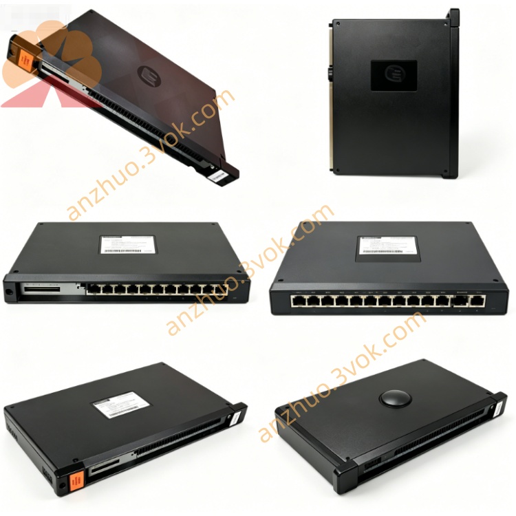
The rear edge connector interfaces with the AutoMax backplane to receive power and enable high-speed data communication with the main controller via the proprietary AutoMax bus protocol. The front panel is equipped with a dedicated resolver connector for field wiring and status LEDs indicating power, signal lock, and fault conditions. No additional external communication ports are provided; all data exchange occurs through the backplane.
Core Functions
It conditions raw resolver signals to filter noise and interference. It converts analog resolver signals into precise digital angular position and velocity data. It provides 12-bit single-turn and 2-bit multi-turn resolution for accurate motion feedback. It monitors input signal health and reports faults (e.g., signal loss, overspeed) to the system. It supports configurable sampling rates to match diverse motion control requirements. The B revision enhances stability in high-electrical-noise environments and reduces signal drift over time.
Application Scenarios
It is designed for AutoMax/DCS-5000-based automation systems requiring high-precision rotary motion feedback, especially in harsh conditions. Typical applications include steel mill drives, paper machine rolls, industrial cranes, machine tools, packaging machinery, and material handling equipment. It is suitable for environments with high electrical noise, vibration, and moderate temperature fluctuations.
Operation and Maintenance Instructions
Power off the system before installing or removing the module. Insert the module into the designated rack slot and ensure firm backplane contact. Connect resolver cables to the front connector per wiring diagrams, verifying proper shielding and grounding. Keep the operating environment clean, dry, and well-ventilated, avoiding dust, moisture, and corrosive substances. Periodically inspect cables and connectors for wear or damage. Do not disassemble or modify the module. Replace with the same model if faults occur to maintain system accuracy and reliability.
Get a Quote