RELIANCE 57C-410-D four-channel galvanically isolated analog output module
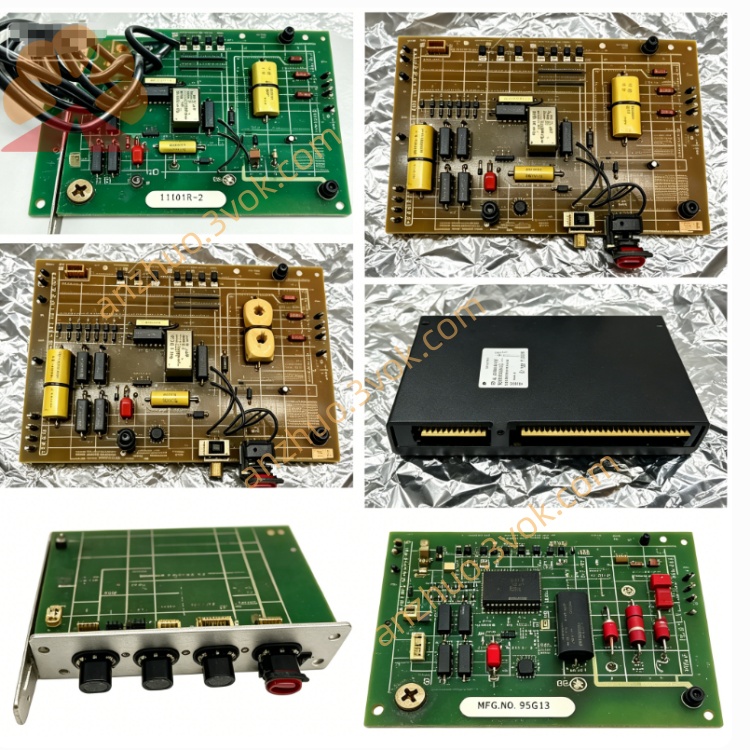
The RELIANCE 57C-410-D is a four-channel galvanically isolated analog output module compatible with AutoMax and DCS 5000 industrial control systems. It adopts a standard single-slot rack mounted structure. This module converts digital control signals from the main controller into standard industrial voltage and current signals to drive field actuators. With reliable circuit design and basic protection performance, it delivers steady output and works continuously in conventional industrial environments for routine process regulation and automatic control.
Description
Product Overview
The RELIANCE 57C-410-D is a four-channel galvanically isolated analog output module compatible with AutoMax and DCS 5000 industrial control systems. It adopts a standard single-slot rack mounted structure. This module converts digital control signals from the main controller into standard industrial voltage and current signals to drive field actuators. With reliable circuit design and basic protection performance, it delivers steady output and works continuously in conventional industrial environments for routine process regulation and automatic control.
Model Definition
RELIANCE is the brand of industrial control products. 57C represents the series of I/O modules and supporting components for the AutoMax platform. 410 refers to the base model code for four-channel analog output modules. The suffix D stands for standard hardware revision D. This version maintains full structural and functional compatibility with other modules in the 57C410 series and matches all standard system racks and firmware.
Technical Parameters
This module is equipped with four independent analog output channels. It supports multiple common voltage output ranges and standard 4-20mA current output. It adopts 12-bit resolution for voltage output and 11-bit resolution for current output, with stable signal conversion accuracy. Galvanic isolation is applied between internal logic circuits and field circuits as well as between different channels. Each channel is fitted with a built-in low-pass filter to reduce signal interference. The module obtains working power from the rack backplane. The operating temperature ranges from 0 degrees Celsius to 60 degrees Celsius, and it has standard vibration resistance and IP20 protection level suitable for general industrial sites.
Interface and Communication Configuration
The rear connector connects to the rack backplane to receive power and complete data transmission with the main controller. The front panel is equipped with screw terminals for connecting field equipment. Each channel is equipped with status indicator lights to display real-time operating conditions. All data and control commands are transmitted through the AutoMax dedicated bus protocol. There are no additional external communication ports, and all signal interaction is finished via the rack backplane.
Core Functions
It converts digital control instructions into analog signals to drive regulating valves, frequency converters and other field devices. The isolation structure prevents external electrical interference and faults from affecting the main control system. The internal filter ensures smooth and stable output signals. It monitors the operating state of each channel in real time and feeds back fault and abnormal information to the system in a timely manner. Users can configure the output type and range of each channel through system software to adapt to different on-site device demands.
Application Scenarios
This module is widely applied in automation projects built on AutoMax and DCS 5000 systems, including steel production, papermaking, chemical processing, power generation and water treatment industries. It is mainly used in conventional process control loops that require analog output signals, and fits most standard field actuators and regulating equipment in common industrial environments.
Operation and Maintenance Instructions
Disconnect the system power supply before installing or removing the module. Insert the module into the specified rack slot and confirm the connection with the backplane is firm and reliable. Connect field cables to corresponding terminals in accordance with wiring requirements and carefully check signal polarity. Keep the operating environment clean, dry and well ventilated, and stay away from dust, moisture and corrosive substances. Regularly inspect terminal connections and status indicators. Do not disassemble or modify the module without permission. Replace it with the same model promptly once faults occur to ensure normal operation of the whole control system.
Get a Quote