
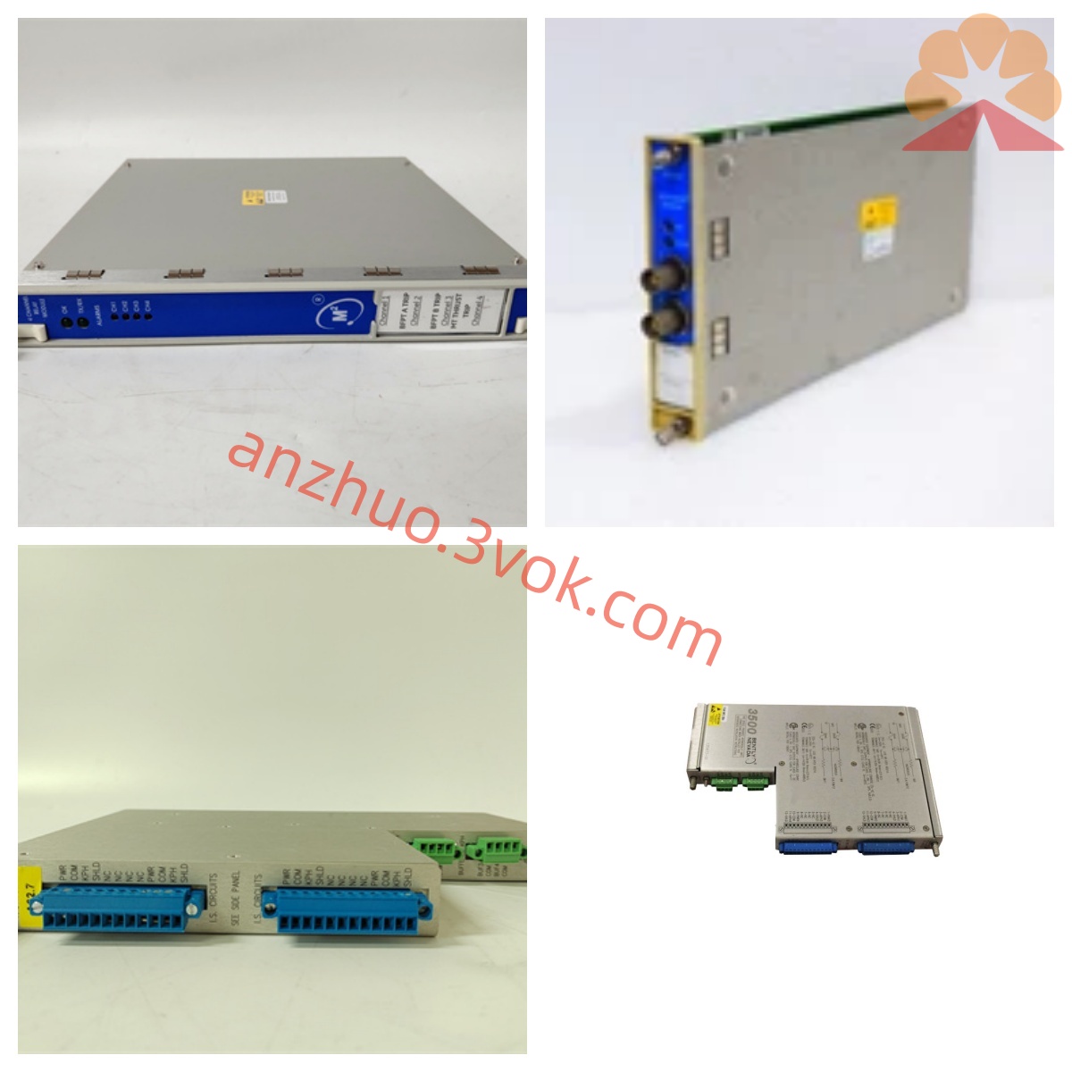
Bentley 3300/16-11-01-00-00-01-02 Dual-channel Vibration Monitor Detailed Product Description
Description
Bentley 3300/16-11-01-00-00-01-02 Dual-channel Vibration Monitor Detailed Product Description
I. Product Overview
The Bentley 3300/16 is a rack-mounted monitoring module within the Bentley Nevada 3300 series of rotating machinery protection system. The current model 3300/16-11-01-00-00-01-02 is a customized configuration version. The product strictly follows the API 670 industrial standard. The equipment adopts a 19-inch standard cabinet single-slot modular design, with a plug-in structure that can be directly installed in the 3300 series dedicated system rack, and is fully compatible with the same series of eddy current probes, preamplifiers, extension cables, and power supply components. This module is mainly used in steam turbines, gas turbines, centrifugal compressors, large motors, fans, industrial pump sets, etc. in the power, petrochemical, metallurgical, coal chemical, etc. industries. It focuses on dual-channel radial vibration monitoring, integrating alarm interlock, loop diagnosis, local display configuration, etc. It is the core equipment for rotating machinery shaft system, bearing condition monitoring and safety protection.
II. Model Code Interpretation
3300/16 is the main product model, defined as a dual-channel vibration monitor. The model suffix consists of seven two-digit codes, corresponding to channel type, measurement range, analog output, alarm logic, sensor diagnosis, hardware version, certification and additional functions. The specific meanings of each segment are as follows.
The first segment code 11 represents channel configuration, which is a basic dual-channel radial vibration input configuration. The two channels are independent and specifically collect axial radial vibration signals, suitable for conventional X and Y direction vibration monitoring scenarios.
The second segment code 01 represents measurement range, with the standard vibration range being 0-1mm (peak-to-peak), suitable for high-speed shaft systems and precise small-sized rotating equipment with strict vibration control requirements.
The third segment code 00 represents analog output configuration. This model does not have standard analog output, only retaining on/off alarm and local display functions.
The fourth segment code 00 represents alarm logic. It adopts the factory default general alarm logic and does not have configured channel voting, special interlock, etc. custom functions.
The fifth segment code 00 represents sensor loop diagnosis. The standard full loop fault diagnosis function is enabled, allowing real-time monitoring of probe, extension cable, preamplifier operation status.
The sixth segment code 01 represents hardware version. It is a specified customized hardware version, different from the general standard version hardware, suitable for specific installation and structural requirements.
The seventh segment code 02 represents certification and additional functions. It is equipped with specialized industry certification and supporting function configuration to meet specific working conditions and safety regulations requirements.
III. Core Functions
1. Dual-channel Independent Vibration Collection
The equipment is equipped with two completely independent measurement channels, which can be connected to two vertically arranged eddy current probes to collect radial vibration data in the X and Y directions of the equipment. The signal processing and logic judgment of the two channels do not interfere with each other, and the abnormality of one channel will not affect the normal operation of the other channel. The dual-channel architecture enhances system redundancy and operational stability.
2. Shaft System Fault Warning Identification
The equipment continuously monitors the amplitude changes of axial radial vibration and can effectively identify typical faults such as rotor imbalance, shaft misalignment, bearing wear, oil film vortexing, foundation loosening, shaft bending, etc., capturing abnormal conditions in advance, avoiding vibration over-limit, shaft friction, bearing burnout, and unplanned shutdown of the unit, etc. major safety accidents.
3. Graded Alarm and Interlock Protection
Each channel is independently configured with one warning relay and one danger relay. The warning threshold and danger trip threshold can be set separately through local buttons. The rated specifications of the relay contacts are 250VAC/3A. The contact mode supports on-site switching between normally open and normally closed states. According to the protection requirements of the unit, a hierarchical alarm and emergency shutdown control circuit can be built.
4. Full-state Diagnosis of the Sensing Circuit
An internal real-time circuit detection mechanism is built-in, continuously monitoring the entire sensing system consisting of eddy current probes, high-frequency extension cables, and preamplifiers. When faults such as open circuit, short circuit, signal beyond the measurement range, or abnormal power supply occur in the circuit, the equipment immediately triggers a sensor fault alarm, locks the abnormal data, and avoids false alarms and mis-tripping caused by sensor faults.
5. Local Display and Parameter Configuration
The body is equipped with an LED digital display and operation keys. Maintenance personnel can view real-time vibration values, circuit voltage, alarm status, and channel operation status on-site. The vibration range, alarm threshold, frequency response, relay action mode, and fault determination rules can all be set locally. After parameter setting, the parameters are automatically stored, and the data is not lost even in the event of a power outage. No external upper-level software is required to complete on-site debugging.
6. Programmable Frequency Response
The device is equipped with two selectable frequency response modes. The low-frequency mode is suitable for low-speed and heavy-load rotating equipment, while the high-frequency mode is suitable for high-speed turbine units. It can match the vibration frequency characteristics of different rotational speed equipment, ensuring measurement accuracy under all operating conditions.
IV. Working Principle
This module operates based on the non-contact eddy current measurement principle. A high-frequency alternating current is introduced into the eddy current probe, and when the probe approaches the surface of the metal shaft, the metal layer will generate eddy current. When the shaft system rotates and produces radial vibration, the gap between the probe and the shaft body changes dynamically, directly altering the eddy current intensity and the equivalent impedance of the probe. The signal change is transmitted via a high-frequency coaxial extension cable to the preamplifier, which completes signal amplification, shaping, temperature compensation, etc., and outputs a linear DC voltage signal sent to the 3300/16 monitoring module.
The internal circuit of the module analyzes and processes the input signal, extracts the dynamic vibration components, and converts them into vibration peak-to-peak values. The system compares the measured values with the preset warning and danger thresholds. When the set value is reached, the corresponding relay is driven to act, and a switch quantity interlock signal is output. This model has no external analog output. All data is presented only through the local display. The two channels independently complete signal processing and logic determination, combined with the circuit diagnosis function, to achieve stable and reliable vibration monitoring and equipment protection.
V. Main Technical Parameters
1. Input and Compatibility System
The entire unit is equipped with two independent eddy current signal input interfaces, compatible with Bently 3300XL series eddy current probes, 330180 series preamplifiers, and 330130 series high-frequency extension cables. The input impedance of the equipment is 10kΩ, fully matching the output characteristics of the accompanying sensing equipment; the standard working gap voltage range is -4VDC to -20VDC, and the standard working point is -12VDC.
2. Measurement Performance Parameters
The standard vibration measurement range is 0-1mm (peak-to-peak), and on-site small-range measurement range correction is supported. The full-scale measurement error in normal temperature environment is ≤±1%, the measurement resolution can reach 0.001mm, meeting the requirements for precise vibration monitoring. The frequency response is divided into two modes, 1-600Hz and 4-4000Hz, covering various rotational equipment scenarios from low speed to high speed.
3. Output Electrical Parameters
This model has no 4-20mA, 0-10VDC, etc., analog output. The relay output is 1 warning and 1 danger per channel, with contact withstand voltage of 250VAC, rated current of 3A, and can be switched between normally open and normally closed modes on-site programming.
4. Power Supply and Power Consumption The equipment is powered by -24VDC direct current, and the allowable voltage fluctuation range is ±10% of the rated value. The normal operating power consumption of the entire machine is approximately 6W.
5. Environmental Parameters
Operating environment temperature: 0℃~60℃; Storage environment temperature: -40℃~85℃; Operating environment relative humidity: ≤95%; There is no condensation, no corrosive gas, and no large amount of dust in the environment. The product has corresponding safety regulations certification and overall performance complies with API 670 standards.
6. Mechanical Structure Parameters
It adopts a 19-inch standard rack installation structure, with a single-slot plug-in design. The total weight of the equipment is approximately 1.5kg. The body is designed with industrial-grade anti-vibration and anti-electromagnetic interference, capable of adapting to complex industrial site conditions.
Six. Installation and System Configuration
1. Rack Installation
The module is of plug-in structure. It can be directly inserted into the idle slot of the 3300 series dedicated system rack to complete fixation. Installation and disassembly are simple, the layout is regular, and it conforms to the installation specifications of industrial control room cabinets.
2. Sensor Installation
Two eddy current probes are arranged perpendicularly in the outer side of the measured shaft, and the gap between the probes is adjusted to make the gap voltage stable at -12VDC, ensuring that the probes work within the linear measurement range. After installation, lock the fixing components to prevent the probes from moving during operation.
3. On-site Wiring
The equipment wiring includes -24VDC power supply wiring, two sensor signal wiring, and relay interlock wiring. When wiring, strictly distinguish the polarity and signal type according to the terminal markings on the body. After wiring, check the tightness and avoid false connections or incorrect connections.
4. Parameter Configuration
After the equipment is powered on, enter the configuration menu through the panel buttons, and set parameters such as vibration range, warning threshold, danger threshold, frequency response gear, relay contact mode, and fault alarm rules. All parameters are automatically saved and will not be lost upon power off. All debugging work can be completed on-site in real time.
Seven. Typical Application Scenarios
In the power industry, it is mainly used for steam turbine generator sets, gas turbine generator sets, and large generators to monitor the radial vibration of the shaft system, protect the main shaft and support bearings, and ensure the safe operation of the unit. In the petrochemical industry, it is widely used in centrifugal compressors, process turbines, booster pumps, and other key dynamic equipment, preventing damage caused by excessive vibration to the rotor and stator, and protecting against blade damage. In the metallurgical and general industrial fields, it is suitable for large exhaust fans, blowers, and high-speed industrial pumps, real-time monitoring of the shaft system status, and early detection of bearing faults and shaft instability. It is also applicable to various small and medium-sized high-speed rotating machinery, providing vibration monitoring and interlock protection throughout the start-up, load regulation, and steady-state operation cycle.
Eight. Product Features and Advantages
First, the function positioning is clear, focusing on dual-channel radial vibration monitoring, eliminating analog output, with a simple structure, cost optimization, and suitable for scenarios requiring local display and switch quantity interlock. Second, reliability is outstanding, with dual-channel independent operation combined with full-loop fault diagnosis, which can promptly detect probe, cable, and preamplifier faults, effectively reducing false alarms and false trips. Third, measurement accuracy is high, using mature eddy current non-contact measurement technology, with no mechanical wear of the probe, combined with high-precision signal processing circuits, the measurement values are stable, and the parameter drift is small over a long period. Fourth, the working condition adaptability is strong, with industrial-grade hardware design, wide temperature and humidity working range, and anti-vibration and anti-electromagnetic interference capabilities, capable of working continuously in harsh industrial sites. Fifth, operation and maintenance are convenient, equipped with a complete local operation interface, allowing for quick viewing of status, troubleshooting, and parameter modification; modular structure supports rapid spare parts replacement, shortening equipment downtime. Sixth, interface is universal, the relay contact specifications are industry standards, which can directly connect to various unit interlock circuits, and the on-site wiring and logic setup are simple.
IX. Complementary Components
This monitoring module needs to be combined with components of the same series to form a complete monitoring system. The core complementary components include the 3300XL series eddy current probes, which should be selected based on the diameter of the measured shaft and the available installation space; the 330180 series preamplifiers, which are responsible for powering the probes and performing the pre-processing of the raw signals; the 330130 series high-frequency coaxial extension cables, which are used to extend the signal transmission distance and are suitable for the distance between on-site equipment and the control room cabinet. The entire system also requires the 3300 series standard installation racks and the -24VDC dedicated power supply module to provide installation support and a stable working power supply for the monitoring module and sensor components.
Get a Quote