
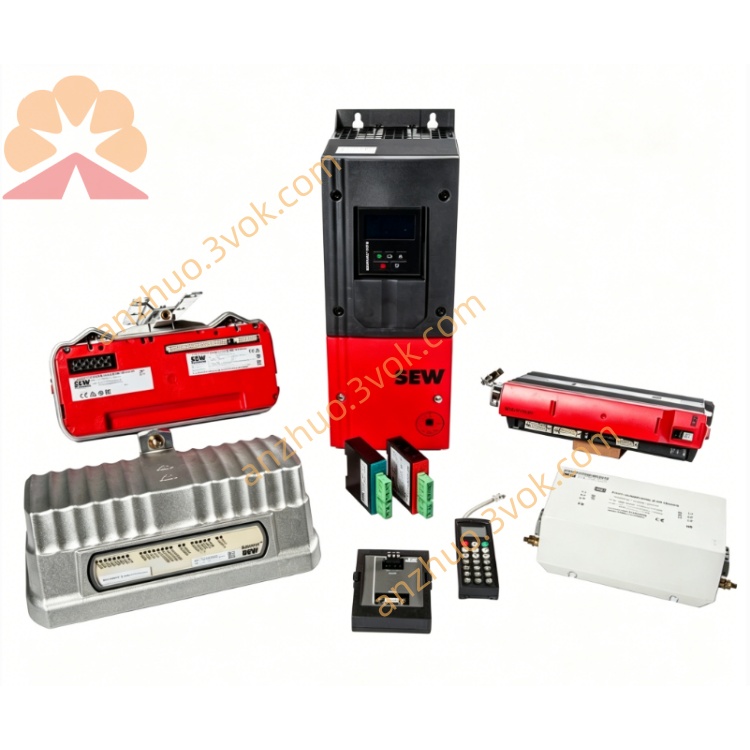
SEW MOVITRANS TVS10A-E06-000-1 Contactless Power Supply
Description
1. General Information
1.1 Product Overview
1.2 Model Code Explanation
TVS10: MOVITRANS stationary connection distributor
A: Protection class I (housing)
E: Increased protection IP65
06: Rated current 60 A (25 kHz)
000: No integrated compensation capacity
1: Flange plate design: 4×M25, 2×M32 connectionseero
1.3 Safety Instructions
Installation/wiring only by qualified electricians.
Disconnect all power before opening; wait ≥5 min for capacitors to discharge.
Risk of electric shock and arc flash; follow IEC 60204‑1.
IP65 for indoor/outdoor use; avoid direct water jets.
Ensure reliable PE grounding; separate power/signal grounds.
Do not modify internal components or bypass safety circuits.
2. Technical Specifications
2.1 Electrical Data
Rated Current: 60 A AC (25 kHz HF)
Frequency: 25 kHz (fixed, for MOVITRANS)
Voltage: Matches TPS converter output (25 kHz, up to 500 VAC)
Connections: 4×M25 (power), 2×M32 (cable entry)
Protection: Overcurrent, short‑circuit, earth fault (via upstream TPS)
Insulation Voltage: 690 VAC
2.2 Mechanical & Environmental
Dimensions (W×H×D): ~180×300×120 mm
Weight: approx. 8 kg
Protection Class: IP65 (dust‑tight, splash‑proof)
Operating Temperature: −20 °C to +50 °C
Storage Temperature: −25 °C to +70 °C
Humidity: ≤ 85% RH, non‑condensing
3. Installation
3.1 Mounting
Mount vertically on rigid, flat surface (wall/frame).
Maintain 100 mm clearance for airflow and cable bending.
Avoid direct sunlight, heat sources, and strong vibration.
Secure with M6 screws (torque: 3.0–3.5 N·m).
3.2 Wiring
HF Input: Connect TPS converter 25 kHz output to M25 terminals; use shielded cables (≥2.5 mm²).
HF Output: Route to TAS transformers/tracks via M25 terminals; shielded cables only.
Grounding: Connect PE first; use low‑impedance ground wire (≥4 mm²).
Cable Entries: Use M32 cable glands; ensure IP65 seal (tighten glands properly).
Pre‑Power Check: Verify no shorts, tight terminals, and correct shielding.
4. Operation
4.1 Commissioning
Confirm all wiring, grounding, and gland seals are correct.
Power on TPS converter; check LED status (no faults).
Verify 25 kHz HF power at TVS output terminals (use oscilloscope).
Check for abnormal noise/heating; run no‑load for 10 min.
Connect TAS modules/tracks; test power transfer and adjust as needed.
4.2 Operating Limits
Continuous operation: ≤ 60 A at 50 °C ambient.
Do not exceed 60 A peak current (risk of overheating/damage).
If fault occurs (overcurrent/overtemperature), shut down immediately.
5. Maintenance
Every 6 months:
Check terminals for looseness, cables/glands for damage/wear.
Inspect IP65 seals; replace if worn (prevent moisture ingress).
Clean dust/debris from enclosure (dry cloth only; no water).
Annually:
Verify insulation resistance (power off, discharge capacitors).
Check internal busbars/connections for corrosion.
Use genuine SEW‑EURODRIVE parts for replacement.
6. Troubleshooting
No HF output: Check TPS power, fuses, wiring, and gland seals.
Overheating: Excessive current (>60 A), poor ventilation, or loose terminals.
Water ingress: Damaged IP65 seals, loose glands, or incorrect mounting.
Fault LED (TPS): Overcurrent (TVS short‑circuit) or earth fault (check grounding).
Get a Quote