
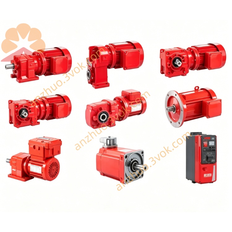
SEW TPS10A040-NF0-503-1 MOVITRANS Stationary Converter
Description
1. General Information
1.1 Product Overview
1.2 Model Code Explanation
TPS10A: MOVITRANS stationary converter, size 2 series
040: Rated power 4 kW
NF0: No integrated filter / basic unit
503: Voltage variant 3×380–500 VAC
1: Standard control version
1.3 Safety Instructions
Installation, wiring, and servicing must be performed only by qualified electricians.
Disconnect all power before opening the enclosure; wait ≥ 5 minutes for DC‑link capacitors to discharge.
Risk of electric shock and arc flash; follow local safety regulations (e.g., IEC 60204‑1).
Do not exceed rated voltage/current; risk of equipment damage and fire hazard.
Protect from moisture, dust, and corrosive environments; indoor use only (IP20).
Ensure reliable protective grounding (PE).
Do not modify internal components or bypass safety circuits.
2. Technical Specifications
2.1 Electrical Data
Input: 3 × AC 380–500 V ±10%, 50/60 Hz
Rated Power: 4 kW
Output: 25 kHz high‑frequency AC (to TAS transformer)
Output Current: 10 A AC (25 kHz)
Control Supply: 24 VDC ±10%, external or internal
Control I/O: 1 analog input (0–10 V / 4–20 mA), 5 isolated binary inputs, 2 binary outputs
Protection: Overvoltage, undervoltage, overcurrent, overtemperature, short‑circuit, earth fault
Efficiency: ≥ 94% at full load
2.2 Mechanical & Environmental
Dimensions (W × H × D): 130 × 350 × 210 mm
Weight: approx. 12 kg
Protection Class: IP20 (control cabinet installation)
Operating Temperature: 0 °C to +40 °C
Storage Temperature: −25 °C to +70 °C
Humidity: ≤ 85% RH, non‑condensing
3. Installation
3.1 Mounting
Install vertically on a rigid, flat mounting plate (control cabinet recommended).
Maintain 100 mm clearance on all sides for cooling airflow.
Avoid heat sources, direct sunlight, and strong vibration.
Secure with M5 or M6 screws (torque: 2.5–3.0 N·m).
3.2 Wiring
Main Input: Connect 3‑phase L1/L2/L3/N/PE to terminals; use 1.5–2.5 mm² copper cables.
HF Output: Connect 25 kHz output to TAS transformer module; use shielded cables (minimum 1.5 mm²).
Control Circuits: Connect 24 VDC, analog, and binary I/O; use twisted‑pair shielded cables for signals.
Grounding: Ensure PE is connected first; separate signal ground from power ground.
Pre‑Power Check: Verify no shorts, correct polarity, and tight terminal connections.
4. Operation
4.1 Commissioning
Confirm correct wiring and grounding.
Power on; check input voltage (380–500 VAC) and LED status indicators.
Use MOVITOOLS® MotionStudio (SEW‑EURODRIVE software) to set parameters and diagnose faults.
Run no‑load for 10 minutes; check for abnormal noise or overheating.
Connect TAS transformer and mobile load; test power transfer and adjust output power as needed.
4.2 Operating Limits
Continuous operation: ≤ 90% load at 40 °C.
Do not run at full load continuously in high ambient temperatures (>35 °C).
If overtemperature or fault occurs, shut down immediately and troubleshoot.
5. Maintenance
Every 6 months:
Check terminals for looseness, cables for damage/aging.
Inspect PE connection integrity.
Clean dust from enclosure and ventilation slots (dry brush only).
Annually:
Verify insulation resistance (power off, discharge capacitors).
Check IGBTs and DC‑link capacitors for aging.
Use genuine SEW‑EURODRIVE parts for replacement.
For internal faults, contact official SEW service.
6. Troubleshooting
No HF output: Check 3‑phase input, fuses, enable signal, and LED fault codes.
Overheating: Excessive load, blocked ventilation, or ambient temperature too high.
Unstable HF output: Loose terminals, poor grounding, or TAS transformer mismatch.
Fault LED ON: Use MOVITOOLS® to read fault code (e.g., F0001 = overcurrent, F0004 = overtemperature).
Get a Quote