
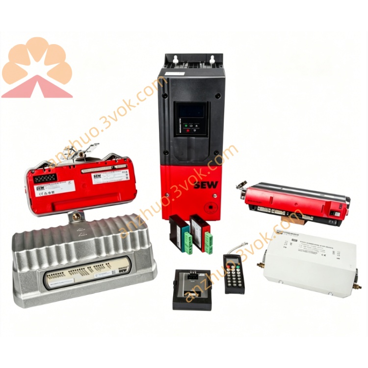
SEW SX60-8-H100-270-MS-RH Gear Motor Unit
Description
1.1 Product Overview
1.2 Model Code Definition
SX60: Series, housing size ≈ 60 mm
8: Wire diameter = 0.8 mm (stainless steel)
H100: Measuring range = 0–100 mm
270: 270° mounting angle / wire exit direction
MS: Multi-turn absolute (gear-based, no battery)
RH: Right-hand wire exit / electrical interface on right
1.3 Safety Instructions
Read this manual before installation and operation.
Do not expose the encoder to strong vibration, shock, or direct moisture.
Ensure stable power supply (10–30 VDC) and correct wiring.
Do not disassemble the encoder; internal gears are precision-calibrated.
Keep the measuring wire clean and free of debris; avoid kinking.
2. Technical Specifications
2.1 Mechanical
Measuring Range: 0–100 mm
Wire Material: Stainless steel, Ø0.8 mm
Max Wire Speed: 1 m/s
Repeatability: ±0.01 mm
Housing Material: Aluminum alloy (anodized)
Protection Class: IP65 (dust-tight, splash-proof)
Operating Temperature: −20 °C to +70 °C
Weight: ≈0.4 kg
2.2 Electrical
Encoder Type: Absolute multi-turn (mechanical gear)
Single-Turn Resolution: 13 bits (8192 steps)
Multi-Turn Range: 12 bits (4096 revolutions)
Total Resolution: 33,554,432 steps
Output Interface: SSI (standard); optional CANopen/Profibus-DP
Power Supply: 10–30 VDC
Current Consumption: <50 mA (no-load)
Electrical Connection: M12 connector (5-pin)
3. Installation
3.1 Mechanical Mounting
Mount the encoder on a flat, rigid surface using the 4 mounting holes (M4 screws).
Ensure the wire exit direction matches the installation (270°, RH).
Attach the wire end to the moving target; maintain straight wire path (no sharp bends).
Tension the wire gently; avoid over-tensioning (max 5 N).
3.2 Electrical Wiring (M12 5-pin)
| Pin | Signal | Description |
|---|---|---|
| 1 | VCC | 10–30 VDC |
| 2 | GND | Ground |
| 3 | DATA+ | SSI data positive |
| 4 | DATA− | SSI data negative |
| 5 | CLK | SSI clock |
4. Operation
4.1 Power-Up
On power-up, the encoder immediately outputs the absolute linear position (no homing required).
The internal gear mechanism retains position during power loss; no battery needed.
4.2 SSI Communication
Clock Frequency: 100 kHz–1 MHz
Data Format: 25-bit (13 bits single-turn + 12 bits multi-turn)
Output Code: Binary (Gray code optional)
4.3 Calibration
Factory-calibrated; no user calibration required.
For field adjustment, use the zero-set function (via SSI command or optional teach button).
5. Maintenance
Regular Inspection: Check wire tension, cleanliness, and connector tightness monthly.
Wire Replacement: If damaged, replace with original Ø0.8 mm stainless steel wire.
Cleaning: Wipe housing with dry cloth; avoid solvents.
Lubrication: Internal gears are pre-lubricated; no additional lubrication needed.
6. Troubleshooting
| Issue | Possible Cause | Solution |
|---|---|---|
| No position output | Power supply failure | Check VCC (10–30 VDC) and wiring |
| Connector loose | Re-seat M12 connector | |
| Position drift | Wire over-tensioned | Reduce tension to ≤5 N |
| Mechanical vibration | Reinforce mounting | |
| SSI communication error | Clock/data wiring reversed | Swap DATA+ and DATA− |
| Excess clock frequency | Reduce clock to ≤1 MHz |
7. Ordering Information
Model: SX60-8-H100-270-MS-RH
Accessories: M12 cable (2 m), mounting bracket, wire end fastener
Get a Quote