
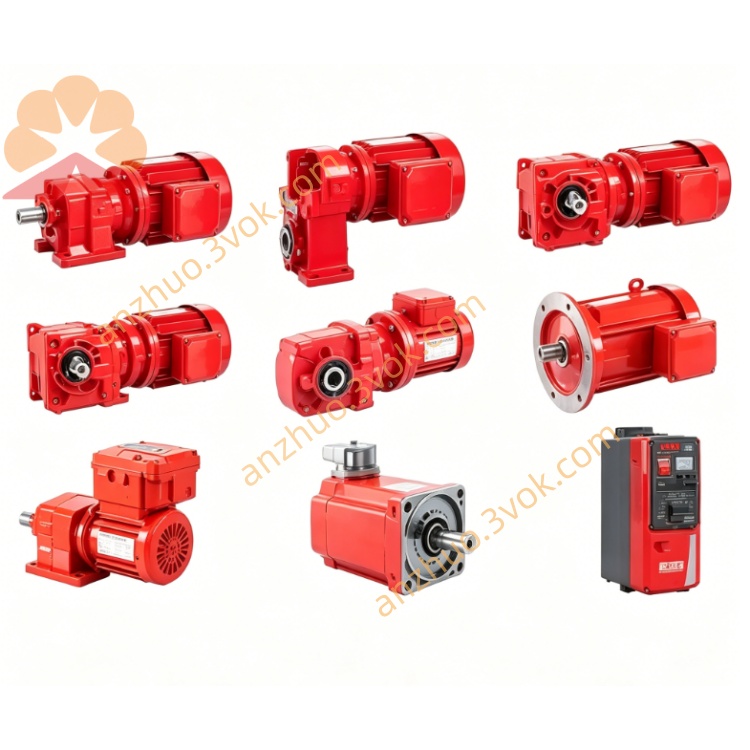
SEW MXM80A-B00-000-00 MOVIAXIS Master Control Module
Description
1.1 Product Overview
1.2 Model Decoding
MXM: MOVIAXIS® Master Module
80A: Series 80A, Hardware Revision A
B00: Basic version (no power stage, standard control hardware)
000: No voltage/power rating (controller-only)
00: Standard configuration, no base options
1.3 Scope of Delivery
1 × MXM80A-B00-000-00 master module
1 × SBUS⁺⁺ backplane connector (pre-installed)
1 × set of mounting screws
1 × quick start guide (digital copy)
Optional: Fieldbus/encoder option cards (sold separately)
1.4 Target Group
1.5 Safety Notes
Electrical Hazard: Disconnect all power before installation/ maintenance. Wait 5 minutes for DC link discharge.
ESD Protection: Use anti-static gloves when handling the module to avoid component damage.
Forced Cooling: Ensure free airflow (≥50 mm clearance top/bottom) to prevent overheating.
Safety Compliance: The module complies with IEC 61800-5-1, UL 508C, and CE (Low Voltage/EMC Directives).
2. Technical Specifications
2.1 General Data
Brand: SEW-EURODRIVE
Type: MOVIAXIS® MXM80A-B00-000-00
Control Supply: 24 VDC ±15%, 0.5–0.9 A (isolated)
Processor: High-performance ARM Cortex-R, 800 MHz
Axis Control Capacity: Up to 64 axes (via SBUS⁺⁺)
System Bus: SBUS⁺⁺ (backplane, 100 Mbps, cycle time ≤125 µs)
Option Slots: 3 × expansion slots (for fieldbus/encoder cards)
Protection Class: IP20 (front), IP10 (rear)
Dimensions (W×H×D): 60 mm × 310 mm × 235 mm
Weight: 1.7–2.3 kg
Operating Temperature: 0 °C to +45 °C (derate 2%/°C above 40 °C)
Storage Temperature: -25 °C to +70 °C
Relative Humidity: 5–95% (non-condensing)
2.2 Control & Communication
Motion Control: Position, speed, torque control; electronic gear, cam profiling, synchronization
Fieldbus Interfaces (via option cards):
PROFIBUS DP (UFF41B)
EtherNet/IP/PROFINET/Modbus TCP (UFR41B)
EtherCAT® (DHR41B/DHE41B, cycle time ≤125 µs)
Diagnostics: 7-segment LED display, 4 status LEDs, integrated data logging, fault code history
2.3 Safety Functions
Safe Torque Off (STO): System-level STO via axis modules (compliant with IEC 61508 SIL 3, PL d)
Safe Stop 1/2 (SS1/SS2): Configurable via safety option cards
Overvoltage/Overcurrent Protection: Integrated hardware/software protection for system components
3. Mechanical Installation
3.1 Mounting Requirements
Orientation: Vertical mounting (DIN rail or panel mount)
Clearance: ≥50 mm top/bottom, ≥20 mm sides for ventilation
Vibration Resistance: ≤0.5 g (10–1000 Hz)
Mounting Surface: Flat, rigid, grounded metal panel
3.2 Installation Steps
Secure the module to the DIN rail or panel using the provided screws (torque: 1.2–1.5 Nm).
Align the SBUS⁺⁺ connector with the adjacent MXA/MXP module and push to lock.
Connect the 24 VDC control supply to the terminal block (observe polarity).
Install option cards (if used) into the 3 expansion slots (push until click).
Verify all connections are tight and secure before powering on.
4. Electrical Connection
4.1 Terminal Block Assignment (24 VDC Supply)
| Terminal | Description |
|---|---|
| +24V | Positive control supply |
| 0V | Negative control supply (ground) |
| PE | Protective earth (connect to system ground) |
4.2 SBUS⁺⁺ Backplane Communication
Connection: Direct plug-in to MXA axis modules, MXP supply modules, or MXC buffer modules
Function: High-speed system communication (axis synchronization, parameter exchange, diagnostics)
Max Nodes: 64 modules per SBUS⁺⁺ segment
4.3 Option Card Connections
Fieldbus Cards: Connect to external PLC/controller via Ethernet/serial cables (refer to option card manual for pinout)
Encoder Cards: Connect to motor encoders (resolver, incremental, absolute) for position feedback
5. Commissioning
5.1 Pre-Commissioning Checks
Verify 24 VDC supply voltage (±15% tolerance)
Check all connections (power, communication, option cards)
Ensure no short circuits or loose wires
Confirm ventilation clearance is sufficient
5.2 Power-On Procedure
Apply 24 VDC control supply to the master module.
The 7-segment display will show "INIT" during boot-up (≈30 seconds).
After boot, the display shows "RDY" (ready) if no faults are detected.
Use MOVITOOLS® Motionstudio software (v6.0+) to connect to the master module via Ethernet/USB.
Configure system parameters (axis count, motion profiles, fieldbus settings)
5.3 Basic Configuration Steps
Scan the SBUS⁺⁺ bus to detect connected modules (MXA/MXP/MXC).
Assign axis numbers and configure motor parameters (type, power, encoder).
Set motion control modes (position/speed/torque) and tuning parameters.
Configure fieldbus communication (IP address, protocol, data mapping).
Test basic motion (jog, homing, synchronization) and verify diagnostics
6. Operation & Diagnostics
6.1 LED Status Indicators
PWR: Green (on = 24 VDC supply OK)
RUN: Green (blinking = module running, solid = idle)
FAULT: Red (on = critical fault, blinking = warning)
BUS: Green (blinking = SBUS⁺⁺ communication active)
6.2 7-Segment Display Codes
RDY: Module ready, no faults
INIT: Booting/initializing
FXXX: Fault code (refer to fault list in system manual)
ADDR: Current module address (SBUS⁺⁺)
6.3 Common Faults & Remedies
F001: Overvoltage (check 24 VDC supply, reduce voltage spikes)
F002: Undervoltage (check 24 VDC supply, tighten connections)
F003: Overheating (increase ventilation, reduce ambient temperature)
F010: SBUS⁺⁺ communication error (check backplane connection, re-seat modules)
F020: Option card fault (reinstall card, check compatibility)
7. Maintenance & Service
7.1 Routine Maintenance
Monthly: Check LED status, clean ventilation slots (remove dust with compressed air, ≤2 bar)
Quarterly: Verify all connections (power, communication, option cards), tighten if loose
Annual: Update firmware via MOVITOOLS® Motionstudio, test safety functions (STO/SS1)
7.2 Firmware Update
Connect the master module to a PC via Ethernet/USB.
Open MOVITOOLS® Motionstudio and select "Firmware Update".
Download the latest firmware from the SEW website (match module model).
Follow on-screen instructions to update (≈10 minutes, do not power off during update)
7.3 Spare Parts
Replacement Module: MXM80A-B00-000-00 (identical to original)
Option Cards: UFF41B (PROFIBUS), UFR41B (EtherNet/IP), DHR41B (EtherCAT®)
Accessories: Mounting screws, SBUS⁺⁺ connectors, 24 VDC terminal blocks
8. Appendix
8.1 Compliance Certifications
CE: Low Voltage Directive 2014/35/EU, EMC Directive 2014/30/EU
UL: UL 508C (Industrial Control Equipment)
RoHS: 2011/65/EU (Restriction of Hazardous Substances)
8.2 Related Documentation
MOVIAXIS® System Manual (756 pages, SEW Doc No. 21219397)
MOVITOOLS® Motionstudio User Guide (SEW Doc No. 11508213)
Option Card Manuals (UFF41B/UFR41B/DHR41B, separate documents)
Get a Quote