
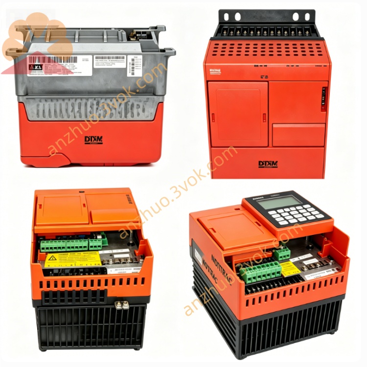
SEW MM15B-503 Decentralized Drive Inverter
Description
1. Product Overview
2. Model Code Explanation
MM: MOVIMOT decentralized drive system
15: Rated power 1.5 kW
B: B-series, second generation
503: 3-phase 380–500 V AC power supply
-00: Standard configuration
Part number: 8230269
3. Technical Specifications
3.1 Electrical Parameters
Input Voltage: 3×380–500 V AC (±10%), 50/60 Hz
Rated Input Current: 3.5 A
Rated Output Power: 1.5 kW
Rated Output Current: 4.0 A
Output Frequency Range: 2 – 100 Hz
Control Modes: U/f control and basic vector control
Digital I/O: 4 programmable digital inputs, 2 programmable digital outputs (24 V DC)
Communication: Integrated RS-485 interface supporting Modbus RTU
Brake Function: Built-in brake control for SEW brake motors
Overload Capacity: 150% rated current for 60 seconds
EMC Performance: No built-in filter; an external Class A EMC filter is required
PWM Frequency: 8 kHz
3.2 Mechanical & Environmental Parameters
Protection Class: IP55
Cooling Method: Natural convection with optimized heat sink
Dimensions (W × H × D): Approximately 135 × 180 × 105 mm
Weight: Around 1.4 kg
Operating Temperature: -25 °C to +40 °C
Storage Temperature: -25 °C to +70 °C
4. Main Features
Equipped with onboard RS-485 communication, enabling convenient network control.
Supports basic vector control, delivering better low-speed torque performance than the A-series.
Wider operating temperature range and improved heat dissipation structure for higher operational stability.
Standard IP55 protection grade, suitable for dusty and humid industrial working conditions.
Simple structure and easy on-site installation and parameter setting.
Noticeable operating noise due to 8 kHz PWM frequency.
5. Product Status & Replacement
MM15B-503: Discontinued and no longer in mass production.
Transitional replacement: MM15C-503 (also discontinued).
Current standard replacement: MM15D-503-00. The D-series comes with built-in EMC filter, 16 kHz low-noise PWM, optional STO function and extended low-temperature resistance, while keeping full compatibility in mounting and wiring.
6. Typical Applications
Logistics conveying systems and sorting equipment
Packaging machinery and auxiliary processing devices
Industrial fans, water pumps and other general automated machinery
Maintenance and renovation of old automation systems
7. Installation & Wiring
7.1 Mechanical Installation
Mount the unit directly on the flange of SEW DRS, DRE or DRP series motors.
Fasten the mounting screws with a torque of 3.0 Nm.
Keep unobstructed ventilation around the heat sink and stay away from heat sources.
7.2 Electrical Wiring
Power Terminals L1, L2, L3, PE: Connect to 3-phase 380–500 V AC power supply and ensure reliable earthing.
Motor Terminals U, V, W, PE: Use shielded cables to connect to the motor terminals.
Control Terminals: Connect 24 V DC power, run/stop and direction signals.
Communication Port: Connect RS-485 cable for Modbus RTU network communication.
EMC Configuration: Install an external Class A EMC filter close to the power input terminals.
8. Commissioning
Inspect all wiring and insulation thoroughly before switching on the power.
Set motor parameters, I/O logic and communication address via DIP switches.
Switch on the main power; steady green LED indicates standby status.
Perform trial run at low speed first, check for abnormal noise and vibration, then adjust to normal operating speed.
9. Status Indication & Common Faults
9.1 LED Status
Steady green: The drive is ready for operation.
Flashing green: The motor is running.
Flashing red: Fault alarm is triggered.
9.2 Typical Faults
Overcurrent: Caused by circuit short circuit, equipment overload or motor failure.
Overvoltage: Resulted from abnormal input voltage or regenerative voltage.
Overtemperature: Caused by blocked ventilation or excessive ambient temperature.
Communication error: Due to damaged RS-485 cable or incorrect address setting.
10. Maintenance
Clean dust on the heat sink every six months to guarantee heat dissipation.
Regularly check the tightness of all terminals and the aging condition of cables.
Replace damaged sealing parts in time to maintain IP55 protection performance.
11. Storage & Disposal
Store the product in a dry and clean environment within the specified temperature range.
Dispose of the product in accordance with local WEEE regulations. Sort metal, plastic and electronic components for professional recycling.
Get a Quote