
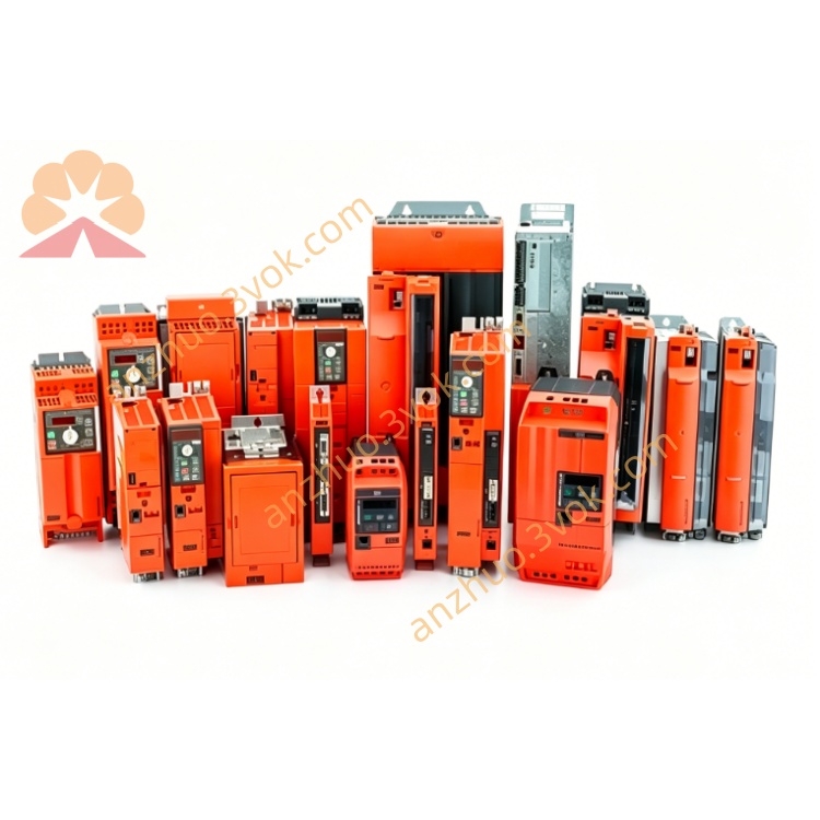
SEW MM15A-503 Decentralized Drive Inverter
Description
1. Product Overview
2. Model Code Explanation
MM: MOVIMOT decentralized drive system
15: Rated power 1.5 kW
A: A‑series (first generation, obsolete)
503: 3‑phase 380–500 V AC
‑00: Standard configuration
Part number: 8241151 (MM15A-503-00)
3. Technical Specifications
3.1 Electrical Parameters
Input Voltage: 3×380–500 V AC (±10%), 50/60 Hz
Rated Input Current: 3.5 A
Rated Output Power: 1.5 kW
Rated Output Current: 4.2 A
Output Frequency Range: 2–100 Hz
Control Mode: U/f (V/f) control (basic, no vector control)
Digital I/O: 3 programmable inputs / 1 programmable output
Communication: No onboard communication (optional module required)
Brake Function: Integrated brake control (for SEW brake motors)
Overload Capacity: 150% rated current for 60 seconds
EMC: No built‑in filter (external EMC filter required, Class A)
3.2 Mechanical & Environmental Parameters
Protection Class: IP55
Cooling Method: Natural convection (basic heat sink)
Dimensions (W×H×D): Approx. 140×180×110 mm
Weight: 1.6 kg
Operating Temperature: 0 °C to +40 °C (no low‑temp rating)
Storage Temperature: ‑20 °C to +60 °C
4. Key Features (vs. Newer B/C/D‑series)
✅ Compact motor‑mounted design (saves cabinet space)
✅ Integrated brake control for SEW brake motors
❌ No built‑in EMC filter (external filter mandatory)
❌ No vector control (only basic U/f)
❌ No communication port (add‑on only)
❌ Louder operation (lower PWM frequency: 8 kHz)
❌ Narrower temperature range (no ‑25 °C rating)
5. Product Status & Replacement
MM15A-503: Obsolete, discontinued (spare parts limited)
Direct Replacement: MM15D-503 (latest D‑series, plug‑and‑play compatible)
6. Typical Applications (Legacy Installations)
Older material handling conveyors
Legacy packaging and labeling machinery
Industrial fans and pumps in existing systems
Anywhere a basic, low‑cost decentralized drive was used
7. Installation & Wiring
7.1 Mechanical
Mount directly to SEW DRS/DRE motor flange
Tighten mounting screws to 2.8 Nm
Ensure ventilation; avoid heat sources (poor thermal design)
7.2 Electrical
Power: L1/L2/L3/PE → 3×380–500 V AC (reliable grounding)
Motor: U/V/W/PE → shielded cable to motor terminals
Control: 24 V DC for run/stop, direction, enable
EMC: External filter required (install close to input terminals)
8. Commissioning
Check wiring/insulation before power‑on
Set motor parameters via DIP switches (basic U/f only)
Power on: steady green = standby
Test at low speed; check noise/vibration (8 kHz PWM is loud)
9. LED Status & Common Faults
9.1 LED
Steady green: Ready
Flashing green: Running
Flashing red: Fault
9.2 Common Faults
Overcurrent: Short circuit, overload, motor fault
Overvoltage: Input surge or regenerative voltage
Overtemperature: Poor ventilation (common in A‑series)
EMC issues: Noise interference (no built‑in filter)
10. Maintenance
Clean heat sink every 3 months (prone to overheating)
Check terminal tightness monthly
Replace damaged seals to maintain IP55
11. Storage & Disposal
Store in dry, clean environment (0 °C to +40 °C)
Dispose per local WEEE directives
Get a Quote