
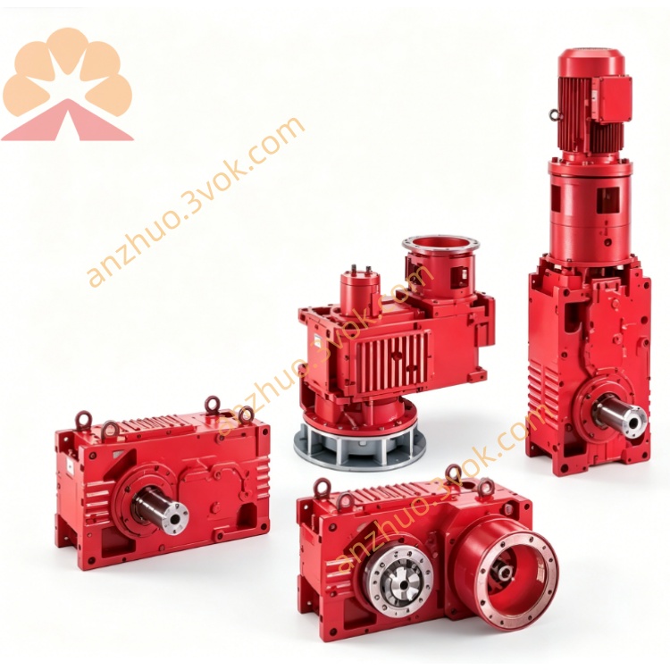
SEW MM11C-503 Decentralized Drive Inverter
Description
1. Product Overview
2. Model Code Explanation
MM: MOVIMOT decentralized drive system
11: Rated power 1.1 kW
C: C‑series (intermediate generation)
503: 3‑phase 380–500 V AC
-00: Standard configuration
Part number: 824118X
3. Technical Specifications
3.1 Electrical Parameters
Input Voltage: 3×380–500 V AC (±10%), 50/60 Hz
Rated Input Current: 2.4 A
Rated Output Power: 1.1 kW
Rated Output Current: 3.2 A
Output Frequency Range: 2–100 Hz
Control Modes: U/f control, basic vector control
Digital I/O: 4 programmable inputs / 2 programmable outputs
Communication: RS‑485 (Modbus RTU, optional)
Brake Function: Integrated brake control for SEW brake motors
Overload Capacity: 150% rated current for 60 seconds
EMC: Built‑in EMC filter (no external filter needed, improved over B‑series)
3.2 Mechanical & Environmental Parameters
Protection Class: IP55
Cooling Method: Natural convection
Dimensions (W × H × D): Approx. 130 × 175 × 100 mm
Weight: 1.4 kg
Operating Temperature: ‑25 °C to +40 °C
Storage Temperature: ‑25 °C to +70 °C
4. Main Features
Built‑in EMC filter simplifies installation and meets industrial EMC standards (B‑series requires external filter).
Compact motor‑mounted design saves control cabinet space.
Improved thermal performance compared to B‑series for better reliability.
Integrated brake control for seamless operation with SEW brake motors.
Robust IP55 enclosure for harsh industrial environments.
Drop‑in compatible with B‑series in mounting and wiring for easy upgrade.
5. Product Status & Replacement
MM11C-503: Obsolete, no longer in production.
Direct Replacement: MM11D-503 (D‑series, latest generation).
6. Typical Applications
Material handling conveyors and logistics systems
Packaging, labeling, and small processing machinery
Industrial fans, water pumps, and general automated equipment
7. Installation & Wiring
7.1 Mechanical Installation
Mount directly on the flange of SEW DRS/DRE/DRP series motors.
Tighten mounting screws to 3.0 Nm.
Ensure adequate ventilation; avoid direct heat sources.
7.2 Electrical Wiring
Power (L1/L2/L3/PE): Connect to 3‑phase 380–500 V AC; ensure reliable grounding.
Motor (U/V/W/PE): Use shielded cables to connect to motor terminals.
Control: 24 V DC for run/stop, direction, and enable signals.
Communication: RS‑485 port for Modbus RTU (optional).
8. Commissioning
Verify all wiring and insulation before power‑on.
Set motor parameters, control mode, and communication address via DIP switches.
Power on; steady green LED indicates standby status.
Test run at low speed; check for abnormal noise/vibration, then ramp to operating speed.
9. Status Indication & Common Faults
9.1 LED Status
Steady green: Ready for operation
Flashing green: Motor running
Flashing red: Fault alarm
9.2 Typical Faults
Overcurrent: Short circuit, overload, or motor winding fault
Overvoltage: Input surge or regenerative voltage
Overtemperature: Poor ventilation or high ambient temperature
Communication error: Cable damage or incorrect address settings
10. Maintenance
Clean heat sink dust every 6 months to ensure heat dissipation.
Regularly check terminal tightness and cable condition.
Replace damaged seals to maintain IP55 protection.
11. Storage & Disposal
Store in a dry, clean environment within the specified temperature range.
Dispose of per local WEEE directives; recycle metal, plastic, and electronic components.
Get a Quote