
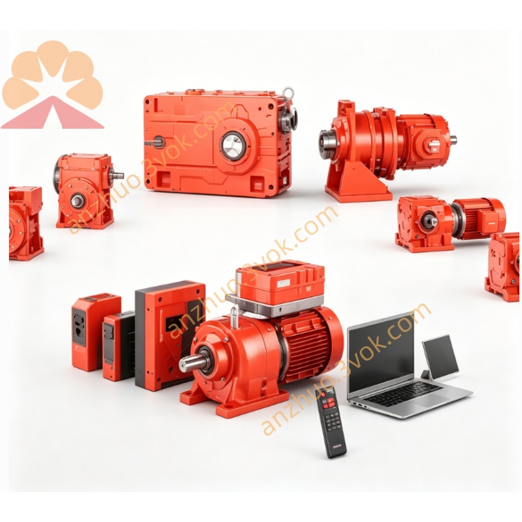
SEW MM03D-503 MOVIMOT Decentralized Drive
Description
1. Product Overview
2. Model Code Explanation
MM: MOVIMOT decentralized drive
03: Rated power 0.37 kW
C: Series C (improved version over MM..A)
503: 3‑phase 380–500 V AC supply, standard control
‑00: Standard version (common full model: MM03C‑503‑00)
3. Technical Specifications
3.1 Electrical
Input: 3×380–500 V AC (±10%), 50/60 Hz
Rated output power: 0.37 kW
Rated output current: 1.3 A
Output frequency: 0–400 Hz
Control modes: VFC (vector) / U/f (selectable)
Communication: RS‑485 (integrated)
Digital I/O: 4 inputs / 2 outputs (programmable)
Safety: Optional STO (Safe Torque Off)
Brake control: Integrated brake management (for SEW brake motors)
Overload: 150% for 60 s, 175% for 2 s
3.2 Mechanical & Environmental
Protection class: IP55 (dust/water resistant, motor‑mounted)
Cooling: Natural convection
Dimensions (W×H×D): Approx. 120 × 180 × 80 mm
Weight: 2.65 kg
Operating temp: ‑25 °C to +40 °C
Storage temp: ‑25 °C to +70 °C
4. Key Features
Decentralized installation: Mounts directly on motor, reduces cabinet wiring and space.
IP55 protection: Suitable for harsh industrial environments (dust, moisture).
Integrated functions: EMC filter, brake control, motor protection, and RS‑485.
Easy setup: DIP switches and potentiometers for basic configuration (no PC required).
Quiet operation: 16 kHz PWM switching frequency for low noise.
4‑quadrant operation: Standard for motoring and regenerative modes.
5. Typical Applications
Conveyor systems (logistics, food, automotive)
Packaging machinery
Material handling equipment
Small fans, pumps, and general automation
Motor‑integrated drive solutions
6. Installation & Wiring
6.1 Mechanical
Mount on motor flange or rigid bracket (torque: 3.0 Nm).
Ensure free airflow around the unit; avoid direct heat sources.
Tighten mounting screws evenly (3.0 Nm).
6.2 Electrical
Power (L1/L2/L3/PE): 3×380–500 V AC, reliable protective earth.
Motor (U/V/W/PE): Shielded cable to motor terminals.
Control (X6): 24 V DC, direction, enable, fault signals.
RS‑485 (X50): Interface for commissioning and networking.
6.3 EMC Guidelines
Use shielded cables for motor and control lines; ground shields at both ends.
Separate power and signal cables by ≥20 cm to reduce interference.
Complies with EN 61800‑3.
7. Commissioning
Verify all wiring, insulation, and connections before power‑on.
Set DIP switches (S1: RS‑485 address; S2: brake/control mode).
Adjust potentiometers:
f1: Max frequency (0–400 Hz)
f2: Min frequency (2–40 Hz)
t1: Ramp time (0.1–10 s)
Apply main power; green LED indicates standby.
Test run at low speed; check for noise/vibration. Gradually increase to rated speed.
8. Status & Faults
8.1 LED Indications (3‑color)
Green (steady): Ready
Green (flash): Running
Red (flash): Fault
Yellow: Warning (e.g., overheat pre‑alarm)
8.2 Common Faults
F01: Overcurrent (short circuit, overload, motor fault)
F02: Overvoltage (supply surge, regenerative load)
F03: Overtemperature (blocked ventilation, high ambient)
F04: RS‑485 communication error (cable, address mismatch)
F08: Speed monitoring error (motor blocked)
9. Maintenance
Inspect every 6 months:
Clean dust from heat sink and ventilation slots.
Check terminal tightness (torque: 0.8–1.5 Nm).
Verify cable insulation and connector integrity.
Keep firmware updated via SEW MOVITOOLS®.
10. Storage & Disposal
Store in a dry, clean area (‑25 °C to +70 °C); keep original packaging.
Dispose per local WEEE regulations; recycle metal, plastic, and electronic components separately.
Get a Quote